
Product Overview

Hydraulic characteristics
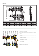
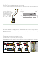
In order to determine the hydraulic characteristics of the circuit, it is necessary to calculate the total head loss suffered by the flow rate of medium
on passing through the devices forming the manifold assembly and the radiant panel circuits.
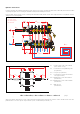
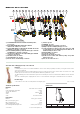
From a hydraulic point of view, the system consisting of the manifold assembly and the circuits can be represented as a set of hydraulic elements
arranged in series and in parallel.
∆P
Tot. = Total loss at the ends of the manifold
(Flow + Return + Loop)
∆PBV = Localised loss at loop balancing valve
(loop flow rate)
∆PLoop = Loop loss (loop flow rate)
∆PSV = Localised loss at panel circuit shut-off
valve (loop flow rate)
∆PManif. F= Distributed loss of the flow manifold
(total flow rate)
∆PManif. R= Distributed loss of the return manifold
(total flow rate)
∆PVB = Ball valve loss
(total flow rate)
∆PTot. = ∆
PBV +
∆
PLoop
+ ∆
PSV
+ ∆PManif. F + ∆PManif. R + ∆PVB x 2
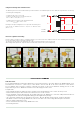
When the hydraulic characteristics of each component and the design flow rates are known, the total loss can be calculated as the sum of the
partial head losses for each specific component in the system, as indicated by the formula (1.1).
G
Loop
∆P
Manif. F
∆P
VB
∆P
Tot.
G
Tot.
∆P
BV
∆P
SV
∆P
Manif. R
∆P
VB
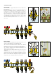
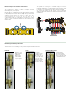
SV = Shut-off valve
BV = Balancing valve
VB = Ball valve
BAGNO
CALEFFI
CAL EFFI
1
2
3
4
L/MIN
1
2
3
4
L/MIN
1
2
3
4
L/MIN
1
2
3
4
L/MIN
1
2
3
4
L/MIN
HOBBY WC
SOGGIORNO
CAMERA
CALEFFI
BAGNOHOBBY WC
SOGGIORNO
CAMERA
CALEFF
∆P
Loop
G
Tot.
∆P
BV
∆P
Loop
∆P
Tot.
∆P
SV
∆P
VB
G
Tot.
∆P
Coll. R
∆P
VB
∆P
Manif. F
G
Loop
(1.1)