
Brochure
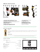

Example of preregulating the valve
Suppose that we need to balance three circuits in the previous example that have the same pressure loss and loop flow characteristics shown
in example (1.2):
Since circuit 2 is the greatest pressure loss in the panel piping, the remaining circuits must be adjusted as follows:
Circuit 2 Circuit 1 Circuit 3
∆P
Loop
= 6.9 psi ∆P
Loop
= 1.13 psi ∆P
Loop
= 4.32 psi
G2 = 1.3 gpm G1 = 0.7 gpm G3 = 1.0 gpm
∆P
MV
= 1.30
2
/1.33
2
= 0.96 psi
∆
P
SV
= 1.30
2
/3.3
2
= 0.16 psi ∆P
SV
= 0.7
2
/3.3
2
= 0.04 psi ∆P
SV
= 1
2
/3.3
2
= 0.09 psi
With the relationship
(1.4): with the relationship (1.3): with the relationship (1.3):
∆PCircuit =
6.9 + 0.96 + 0.16 = 8.02 psi
∆PCircuit = 1.13 + 0.04 = 1.17 psi ∆PCircuit = 4.32 + 0.09 = 4.41 psi
with gr
eatest
pr
essure
loss
HPredetermined ≥
∆
PCircuit = 8.02 psi
with greatest pressure loss
To adjust circuits 1 and 3, we need the
following infor
mation to deter
mine the
adjustment position of the micrometric
valves:
Loop 1
∆
PBV1 = 8.02 - 1.17 = 6.85 psi
G1 = 0.7 gpm
Adjustment position ~ 3
Loop 2
Adjustment position completely open
Loop 3
∆
PBV3 = 8.02 - 4.41 = 3.61 psi
G3 = 1 gpm
Adjustment position ~ 6
∆P
Circuit
with greatest
pressure loss
∆P
1
∆P
BV1
∆P
3
∆P
BV2
∆P
2
H
Predetermined
≥
(psi) (kPa)∆p (psi)
0.1
1
0.2
0.3
0.5
2
3
5
1
10
2
3
5
20
30
0.4
4
0.1
1
0.2
0.3
0.5
2
3
5
0.4
4
1010
50
50
20
100
G (l/h) (
gpm
)
0.1
0.2
0.5
200
0.05
1
2
10
0
8
6
4
2
10
0
8
6
4
2
4 5 6 7 9 101,5 321 8
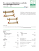
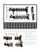
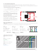
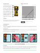
Use of the micrometric balancing valve
The micrometric balancing valves balance each individual circuit in the panels so that the actual design flow is obtained in each one.
Each individual circuit consists of a micrometric balancing valve, panel piping and shut-off valve. The following information must be taken into
account in order to calibrate the system correctly:
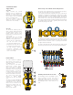
· The flow of fluid that must pass through each circuit (design data).
· The pressure loss that occurs in each circuit in accordance with the flow:
∆
PCircuit =
∆
PLoop +
∆
PSV (1.3)
· The available head on the panel circuit or predetermined head:
HPredetermined ≥
∆
PCircuit =
∆
PBV +
∆
PLoop +
∆
PSV (1.4)
with gr
eatest pressure loss
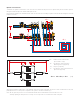
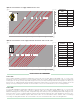
In accordance with the passage of the flow GLoop the
micrometric valve must ensure an additional pressure loss
in all the circuits equal to the difference, indicated as
∆
PBV
(
∆
p micrometric balancing valve).
To allow for an eventual increase in flow, the micrometric
balancing valve of the circuit with the greatest pressure
loss may sometimes be considered as 80% open.
Once the two pieces of information,
∆
PBV and GLoop,
are known for each circuit, the optimal adjustment curve
corresponding to the adjustment position of the valve must
be chosen from the graph.
H
Pr
edetermined
≥ ∆P
Cir
cuit
with greatest
pressure loss
∆P
BV
∆P
Circuit
∆P
Tot
SV
BV