
Brochure
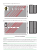
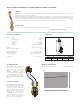
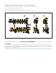

Installation of the differential bypass valve on series 663 and 668 manifolds
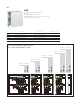
The differential bypass on series 663 or 668 manifolds is mounted by following the procedure below:
1) Remove the drain cock (A) on the upper manifold.
2) Remove the automatic air vent (B) on the lower manifold.
3)
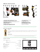
Install the differential bypass (code 668000) on the upper manifold and the lower manifold.
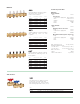
Code 668000
Of
f-center bypass assembly with fixed setting. 1/2”M thr
eaded connections. Brass body and nuts. Copper pipe. P
A check
valve, stainless steel spring, EPDM seals, asbestos-free fibre gaskets. Medium: water and glycol solutions. Maximum
percentage of glycol: 50%. Maximum working pressure: 150 psi (10 bar). Temperature range: 14÷230°F (-10 to 110°C). Fixed
setting pressure: 3.6 psi (2500 mm w.g.).
SPECIFICATION SUMMARIES
CA
LEFFI
CA
LEFFI
CA
LEFFI
CA
LEFFI
10
0
8
6
4
2
10
0
8
6
4
2
10
0
8
6
4
2
10
0
8
6
4
2
CAL EFFI
10
0
8
6
4
2
10
0
8
6
4
2
10
0
8
6
4
2
10
0
8
6
4
2
10
0
8
6
4
2
10
0
8
6
4
2
CAL EFFI
CAL EFFI
10
0
8
6
4
2
10
0
8
6
4
2
10
0
8
6
4
2
10
0
8
6
4
2
CAL EFFI
1 2
A
B
CAL
EFFI
10
0
8
6
4
2
10
0
8
6
4
2
10
0
8
6
4
2
10
0
8
6
4
2
CAL EFFI
CAL EFFI
3
CAL EFFI