
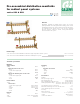
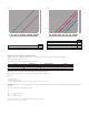
Brochure

Construction details
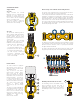
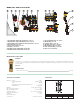
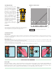
Supply manifold
663 series
Supply manifold has manual
balancing valves for regulating flow
delivered to system circuits. The
balancing is accomplished by turning
an hex wrench into the balancing
valve in each supply outlet.
The chart on page 7 shows the
number of turns for reaching the
desired value of flow and
∆p.
668 series
The micrometric balancing valve is
made of plastic (POM) and features
an upside down V channel (1) to
provide greater precision when
regulating the flow delivered to the
system circuits.
This solution offers the following
advantages with respect to the
traditional conically shaped valve:
- greater precision, particularly for
the low flow rates usually
encountered in radiant system.
- proportional flow rates due to the
V channel in the fluid passage.
- the chart on page 7 shows the
micrometric graduated scale
number for setting the desired
value of flow and
∆p.
Return manifold
The return manifold is equipped
with manual shut-off valves (1)
which ar
e used to shut of
f the flow
to individual circuits.
They can also be used with a
ther
moelectric actuator which,
when used with an ambient
thermostat, maintains the ambient
temperature at the set limits when
ther
mal load varies. The stem (2)
is made of polished stainless steel
to minimise friction and prevent
harmful encrustation from forming.
The control device upper part
featur
es a double EPDM
O-ring seal (3) – (4) on the sliding
stem.
The valve (5) is made of EPDM and
is moulded to optimise the hydronic
characteristics of the valve and
reduce noise to a minimum as the
fluid passes through and as it
gradually opens and closes when
operating with a
thermo-electric actuator.
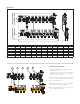
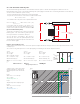
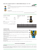
Exterior shape of the manifolds and mounting brackets
The exterior of the manifold deserves special mention because it
can be cast in any shape to meet any requirements.
In the example shown below, indentations have been created in the
manifold to correspond to the plastic pipes exiting from the upper
manifold, thus partially accommodating the pipes and reducing
their overall thickness. This does not interfere with the pressure loss
values because the sections with the indentations (a) are equal to
the sections in which the pipes are branched (b) and (c) and where
the regulating parts (micrometric regulating and shut-off valve)
obstruct the passage of the fluid.
The partial accommodation of the pipes in the indentations created
in the manifold is further enhanced by the angle of the mounting
brackets, which are slanted to create a 1” (25 mm) offset between
the upper and lower manifolds.
As shown in the figure below, this offset positions the pipes so that
they perfectly match the profile of the manifold during installation.
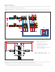
End fitting and automatic air vent valve
The end fitting consists of a fill/drain cock (1)
and an automatic air vent valve with a
hygr
oscopic safety cap (2). It has been
specifically designed to close the air vent valve
automatically if there is water near the vent
itself.
1
1
3
4
2
5
a
b
c
CALEFFI
CALEFFI
10
0
8
6
4
2
1” (25 mm)
CAL EFFI
CAL EFFI
CA
LEFFI
CALEFFI
10
0
8
6
4
2
10
0
8
6
4
2
10
0
8
6
4
2
10
0
8
6
4
2
10
0
8
6
4
2
10
0
8
6
4
2
10
0
8
6
4
2
10
0
8
6
4
2
10
0
8
6
4
2
10
0
8
6
4
2
10
0
8
6
4
2
10
0
8
6
4
2
10
0
8
6
4
2
10
0
8
6
4
2
2
1
CALEFFI