
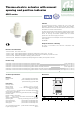
Product Overview
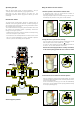

Installation
- The thermo-electric actuator should be tightened by hand without
the use of tools.
- The thermo-electric actuator should not be dismantled for
possible repairs. Tampering with it leads to permanent damage.
- The actuator should always be fitted in a horizontal or vertical
position, but never upside down. In chilled water circuits,
positions which allow condensation to get into the actuator are not
advisable.
- For the actuator to work correctly, the electric system must be
sized according to the starting current.
- If it is necessary to make regulations of several zones by
means of actuators in parallel with the same thermostat, an
intermediate relay could be needed to avoid electric overloads.
- When assembling with a zone valve or manifold in a box, leave a
gap of at least 20 mm between the thermo-electric actuator and
the frame for any replacement or maintenance work.
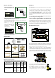
Recommendations for use
When the thermo-electric actuators are installed on devices that
automatically shut off the heating terminals, it is always advisable to
use a differential by-pass to control overpressure in the system
during the partial or total closing phase of the circuits:
· Available as an accessory for 668...S1 series preassembled
manifolds is the differential by-pass with fixed setting 2500 mm w.g.
code 668000S1; available as an accessory for 662 series
preassembled manifolds
is the differential by-pass with fixed setting
2000 mm w. g.
code 662000; available as an accessory for
663 series preassembled manifolds
is the
differential by-pass with fixed setting 2000 mm w. g.
code 663000.
· For centralised installations or installations with
risers, a differential by-pass valve is available with
an adjustable setting of 1 to 6 m w.g., 519 series.
Hydraulic characteristics
Table of hydraulic characteristics of control 6563 + valve body
Coupling table
*
Maximum pressure differential assured by the servo control for regular operation
Zone valve (straight/bypass)
Manifold for radiant panel
systems and radiators
676
677
678
662
663
666 S1
668 S1
670/671
1/2” – 1”
1”
1 1/4”
1 1/4”
1 1/4”
1”
370
370/100
370/100
410
287
250
250
240
12
12
12
18
25
25
25
25
DNseries
656302, 656304,
656312, 656314 +
kv
0,01
(l/h)
D
p
max
*
(m w.g.)
C
A
L
E
F
F
I
C
A
L
E
F
F
I
°
C
0
20
8
0
6
0
40
°C
0
2
0
80
60
40
CALEFFI
CALEFFI
CALEFFI
Min. 20 mm
Cod. 668000S1
BAGNO
C
ALEFFI
CALEFFI
1
2
3
4
L/MIN
1
2
3
4
L/MIN
1
2
3
4
L/MIN
1
2
3
4
L/MIN
1
2
3
4
L/MIN
HOBBY WC
SOGGIORNO
CAMERA
C
ALEFFI
BAGNOHOBBY WC
S
OGGIORNO
CAMERA
CALEFF
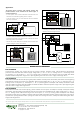
Electric connections
· Electrical connections for
codes 656302, 656304 and
656344.
· Electrical connections for codes 656312, 656314 and 656354.
Wiring diagram with pump disconnection.
The auxiliary microswitch can be used to turn off the pump when
the user circuits need no
heat and the valves are
closed.
If the pump consumption
exceeds the capacity of the
contacts equal to 0,8 A, an
intermediate contactor
should be used.
The auxiliary microswitch shuts off for an average thermo-electric
actuator opening value of 80%.
Ω
BLUE
B
ROWN
BLACK
BLACK
Ω
BLUE
BROWN
656302 656344
656304 656354
656312
656314
676 677 678
666-668 S1
670-671
mH
2
O
1
2
3
4
5
6
RT
N
F
1
0
RT
N
F
1
0
662
663