
Brochure
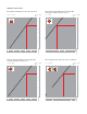

4b. In installations with chilled water, with the risk of
condensation, the actuator must be installed with
the control stem vertical.
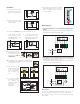
5. The actuator can be
fitted on the valve body
in the two positions
shown. Fastening is
with
a stainless steel
clip.
6. In a box installation
leave a gap of at least
1¼” between the
actuator and frame for
replacement,
if
necessary, or
maintenance.
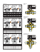
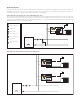
Wiring diagrams
1. Connection diagram for room thermostat (RT) and electric
supply.
The illustrated connection permits opening and closing the valve
according to the ambient thermostat signal.
2. Pump disconnection diagram when no zone is in operation.
This diagram, using the auxiliary microswitch,
permits turning off
the pump when the zone valve is closed.
If the pump has an input current greater than 0,8 A (170 VA) it is
necessary to use an intermediate relay.
M
CLOSE
OPEN
RT
N
L
Max
0,8 A
ACTUATOR
M
CLOSE
OPEN
RT
N
L
Max
0,8 A
ACTUATOR
Microswitches
The motor is equipped with limit microswitches that cut off the
electricity supply on reaching the valve open/closed positions.
The auxiliary microswitch turns on for an average valve opening
value of 80%.
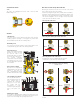
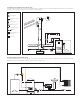
Installation
1. The two-way valve can be
installed either on the flow
pipe or on the return pipe.
LOAD
2.
The three-way valves with
by-pass must be installed
on the flow pipe.
LOAD
a.
on the flow in the diverter
/mixer position (common
inlet
AB and outlets A or B)
and ON/OFF mode
b. on the return in the
mixer
position (that is inlets
on A
and B and common outlet
AB) and ON/OFF mode
3. The three-way diverter valves can be installed as shown:
4.
The valve must be
installed with the control
stem in the horizontal or
vertical position, never
overturned.
LOAD
LOAD
A
AB
B
A
AB
B
Vertical stem
Horizontal stem
AB
AB
AB
AB
min. 1¼”
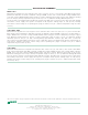
6. To prevent the actuator from reaching
high temperatures, where the zone
valve is installed there should be
constant ventilation.
C
A
L
E
F
F
I
C
A
L
E
F
F
I
C
A
L
E
F
F
I
C
A
L
E
F
F
I
Max
0,8 A
M
OPEN
CLOSE
LN