
Product Overview
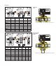

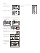

Wiring diagrams
1. Connection diagram for room SPDT thermostat (RT) and
electric supply.
The illustrated connection permits opening and closing the valve
according to the ambient thermostat signal.
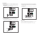
2. Connection diagram for single contact thermostat (RT) or
on-off switching device.
If the termostat has only a single contact, or on-off switch is used,
install a SPDT relay as shown below.
M
CLOSE
OPEN
RT
N
L
Max
5 A
ACTUAT OR
M
CLOSE
OPEN
RT
N
L
Max
5 A
ACTUAT OR
M
CLOSE
OPEN
RT
N
L
Max
5 A
ACTUAT OR
M
CLOSE
OPEN
RT
N
L
Max
5 A
ACTUAT OR
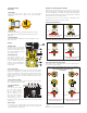
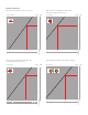
Micro-switches
The motor is equipped with limit micro-switches that shut off the
motor when reaching the valve open/closed positions.
The micro-switch activates at approximately 80% valve opening.
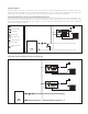
3. Pump disconnection diagram when no zone is in operation.
This diagram, using the micro-switch,
turns off the pump when the
zone valve is closed.
If the pump has an input current greater than 5 A (24 V), use an
intermediate relay.
M
CLOSE
OPEN
24 VAC
Relay
N
L
Max
5 A
ACTUATOR
RT