
Install Instructions

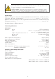

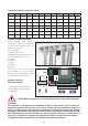

ºF ºC Ω ºF ºC Ω ºF ºC Ω ºF ºC Ω
-5 -20 100254 60 15 15310 130 54 3049 200 93 829
5 -15 72937 70 21 11882 140 60 2489 210 99 702
15 -10 53669 80 27 9297 150 65 2044 220 104 598
25 -4 39919 90 32 7333 160 71 1688 230 110 511
32 0 32648 100 38 5827 170 77 1402 240 115 439
40 4 26100 110 43 4664 180 82 1171 250 121 378
50 10 19900 120 49 3758 190 88 983
Temperature sensor resistance values
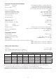
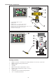
Location of cable connectors
B attery disconne
c
B attery connected
ock disabled
factory s etting)
B attery c onnec tion
hoc k
on
B attery
1
3
4
5
6
7
9
8
2
When making the electrical
connections, follow this sequence
for wiring the terminal strip and
tightening the seals:
1. Power supply
2. Mixing valve control
3. Mixed outlet temperature sensor
4. Return temperature sensor
5. RS485
6. Relay 3
7. Relay 1
8. Relay 4
9. Relay 2
Strain relief cord connectors (white)
are provided for all 9 controller
housing holes. Clear plastic plugs
also provided for unused holes.
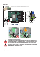
Enabling functions-
Dipswitch settings
-Thermal Shock enable/disable.
-Internal battery (do this during
installation)
PIN
disable
Reset
Appliance fuse
400 mA-250Vdelayed
Mixing valve fuse
1 A - 250 V delayed
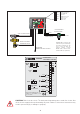
Relay contacts
Electric
supply
24 V
Mixing
valve
Battery connected
Battery disconnected
Battery connection
Thermal shock
activation
Shock
enabled
Shock
disabled
(factory setting)
Temperature
sensors
Mixed outlet
Return
Common
Relay 1
Relay 2
Relay 3
Relay 4
Closes
Common
Opens
Earth
Earth
Neutral
Live
PIN code
disabling button
Reset button
Screw to close
the front cover
with hole
for lead-sealing
RS485
Interface
terminal
Microswitch
for enabling
thermal shock
function
Temperature
sensor terminal
Battery
To remove the electrical wiring base, turn it round and extract it from its housing.
–
+
ATTENTION: If the battery is not activated the battery alarm will be displayed.
CAUTION!
The controller is congured to automatically execute a daily rotation cycle to ensure ef-
cient ball operation and cleaning. This occurs directly after the disinfection program, if
active, or after 24 hours have elapsed if disinfection is not active. Deactive this function
through the ANTI-CLOG setting by entering the release code 5566 and conrming with ON-
OFF. Eliminating this function increases the risk of deposits forming on moving parts of
valve. If it is necessary to eliminate the disinfection function as well, proceed as follows:
1. disable the ANTI-CLOG function; 2. eliminate the disinfection function.
10