
Technical Sheet


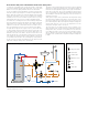


Kv = 2.6
0.1
10
0.01
0.1
0.02
0.03
0.02
0.05
0.2
0.5
0.05
1
0.2
0.3
0.5
20
50
∆p (psi)
G (l/min) (
gpm
)
10
2
3
5
20
0.01
0.1
0.02
0.03
0.05
1
0.2
0.3
0.5
(psi) (bar)
10
2
3
5
20
1
0
.
1
0
.2
0.5
0
.05
10
2
5
2
0
0.001
0.01
0.002
0.003
0.005
0.1
0.02
0.03
0.05
1.0
0.2
0.3
0.5
Cv = 3.0
4
0.04
0.4
0.04
0.4
4
0.004
0.04
0.4
41
31
21
11
01
9
8
7
6
5
4
3
2
1
42
32
31
21
11
01
9
8
7
6
5
4
3
2
1
42
32
91
81
71
61
51
41
31
21
11
01
9
8
7
6
5
4
3
2
1
42
2
2
71
61
51
31
21
11
01
9
2
3
0
10
20
30
40
50
60
70
80
90
100
0
10
20
30
40
50
60
70
80
90
100
0
10
20
30
40
50
60
70
80
90
100
0
10
20
30
40
50
60
70
80
90
100
10
ϒ
C
2 min.
hot water
mixed water
cold water
M
I
N
M
A
X
7
1
2
3
Index Point
Flow curve
Use
Caleffi MixCal
™
521 series thermostatic mixing valves are designed to be
installed at the hot water heater. The Caleffi 521 series valve cannot be
used for tempering water temperature at fixtures as a point-of-use valve.
They are not designed to provide scald protection or chill protection
service. They should not be used where ASSE 1070 devices are
required. Wherever a scald protection feature is required, Caleffi 5213
series high performance mixing valves need to be installed. For safety
reasons, it is advisable to limit the maximum mixed water temperature
to 120°F.
Instantaneous production of hot water
Caleffi MixCal
™
521 series thermostatic mixing valves should not be
used in conjunction with boilers giving instantaneous production of
domestic hot water. Their addition would compromise the correct
operation of the boiler itself.
Radiant panel heating systems
Caleffi MixCal
™
521 series thermostatic mixing valves can also be used
for regulating the flow temperature in hydronic and radiant heating
systems, to which it assures a constant and accurate control with ease
of installation.
Temperature stability
The diagram shows the stability of the temperature of the mixed water
on variation of the temperature of the stored water.
Installation
Before installing a Caleffi MixCal
™
521 series three-way thermostatic
mixing valve, the system must be inspected to ensure that its operating
conditions are within the range of the mixing valve, checking, for
example, the supply temperature, supply pressure, etc.
Systems where the Caleffi 521 series thermostatic mixing valve is to
be fitted must be drained and cleaned out to remove any dirt or debris
which may have accumulated during installation.
The installation of filters of appropriate capacity at the inlet of the water
from the mains supply is always advisable.
Caleffi 521 series thermostatic mixing valves must be installed by
qualified personnel in accordance with the diagrams in this brochure,
taking into account all current applicable standards.
Caleffi 521 series thermostatic mixing valves can be installed in any
position, either vertical or horizontal, or upside down.
The following are shown on the thermostatic mixing valve body:
- Hot water inlet, color red and marked “HOT”.
- Cold water inlet, color blue and marked “COLD”.
- Mixed water outlet, marked “MIX”.
Check valves
In order to prevent undesirable backsiphonage, check valves should be
installed in systems with thermostatic mixing valves. As a convenience
for easier installations, the Caleffi 521 “AC” series thermostatic mixing
valves include integral check valves in the hot and cold inlet ports.
Commissioning
In view of the special purpose of the thermostatic mixing valve, it must
be commissioned in accordance with current standards by qualified
personnel using temperature measuring equipment. Caleffi 521519A
and 521619A with integral outlet port temperature gauges provide a
time-saving temperature setting process to get close to the desired
temperature. Use of a digital thermometer is recommended for
determing the final setting of the mixed water temperature. Note: For
MixCal
™
models purchased without the outlet temperature gauge, the
temperature gauge adapter with temperature gauge can be separately
purchased and field installed, code NA10056 for 3/4" models or code
NA10058 for 1" models.
Temperature adjustment
The temperature is set to the required value by means of the knob with
the graduated scale, on the top of the valve.
Locking the setting
Position the handle to the number
required with respect to the index
point. Unscrew the head screw, pull
off the handle and reposition it so that
the handle fits into the internal slot of
the knob. Tighten the headscrew.
Pos. Min. 1 2 3 4 5 6 7 Max.
T (°F) 81 90 100 111 120 127 136 145 152
T (°C) 27 32 38 44 49 53 58 63 67
with: T
HOT
= 155°F (68°C), with: T
cold
= 55°F (13°C), P = 43 psi (13 bar)