
Overview of Primary Product

-
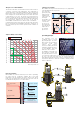
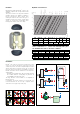
When cleaning, simply unscrew the part of the
body
containing the
automatic air vent (4).
On threaded
models without a
drain, this part
cannot be
removed (5).
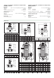
Construction details
The automatic air vent is located at the top of the unit and is
equipped with a long chamber for the floating action. This feature
prevents the impurities present in the water from reaching the seal
seat.
The construction of the
DISCAL
®
deaerator allows it to be
maintained and cleaned without removing the device from the
system. Note the following:
- The moving parts
that control the air
venting are
accessed simply by
removing the upper
cover.(3).
Flanged and weld-end deaerators
are equipped with a cock (A) that
has the dual function of releasing
large quantities of air when the
system is being filled and of
removing the impurities that float
on top of the water.
A drain valve (B) can be
connected at the bottom of the unit
to drain the impurities that have
collected at the bottom of the
deaerator.
A
B
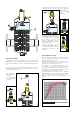
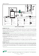
Air separation efficiency
DISCAL
®
devices are capable of continuously removing
the air contained within a hydraulic circuit, with a high
degree of separation efficiency.
The amount of air which may be removed from a circuit
depends on various parameters: it increases as the
circulation speed and pressure values fall.
As illustrated on the graph below, after just 25
recirculations at the maximum recommended speed,
almost all the air artificially introduced into the circuit is
eliminated by the deaerator, with variable percentages
according to the pressure within the circuit.
The small amount which remains is then gradually
eliminated during normal system operation. In conditions
where the speed is slower or the temperature of the
medium is higher, the amount of air separated is even
greater.
0
10
20
30
40
50
60
70
80
90
100
0
100
200
300
400
500
600
700
800
900
1000
1100
1200
Tme
(s)
10
15
20
25
No.
of
recirc.
1 bar
2 bar
3 bar
Air introduced - Air removed - (%)
V = 1 m/s - T = constant
2
4
4
5
3
3
1