
Overview of Primary Product

Operating principle
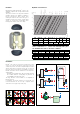
The deaerator uses the
combined action of several
physical principles. The active
part consists of an assembly of
concentric metal mesh
surfaces. These elements
create the whirling movement
required to facilitate the release
of micro-bubbles and their
adhesion to these surfaces.
The bubbles, fusing with each
other, increase in volume until
the hydrostatic thrust is such as
to overcome the adhesion force to the structure. They rise towards
the top of the unit from which they are released through a
float-operated automatic air release valve.It is designed in such a
way that the direction in which the medium is flowing inside it
makes no difference.
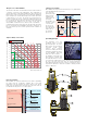
The process of air formation
The amount of air which can remain dissolved in a water solution is
a function of pressure and temperature. This relationship is
governed by Henry’s Law and the graph below allows the physical
phenomenon of the air content release of the fluid to be quantified.
As an example, at a constant absolute pressure of 2 bar, if the water
is heated from 20°C to 80°C, the amount of air released by the
solution is equal to 18 l per m
3
of water. According to this law it can
be seen that the amount of air released increases with temperature
rise and pressure reduction. The air comes in the form of
micro-bubbles of diameters in the order of tenths of a millimetre.
In heating and cooling systems there are specific points where this
process of formation of micro-bubbles takes place continuously: in
the boiler and in any device which operates under conditions of
cavitation.
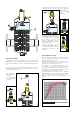
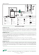
Boiler micro-bubbles
Micro-bubbles are formed continuously on the surface separating
the water from the combustion chamber due to the fluid
temperature. This air, carried by the water, collects in the critical
points of the circuit from where it must be removed. Some of this air
is reabsorbed in the presence of colder surfaces.
Max amount in litres of dissolved air per m
3
of water (l/m
3
)
Water temperature °C
0 20 40 60 80 100 120 140 160
0
5
10
15
20
25
30
35
40
45
50
55
180
1 bar
2 bar
3 bar 4 bar 5 bar 6 bar 7 bar 8 bar
Absolute pressure
Flame temperature
1000°C
W
all temperature
160
°C
Combustion chamber
wall
Boundary layer
Average water
temperature 70°C
Boundary layer
temperature 156°C
FLAME WATER
Micro-bubbles
Graph: Solubility of air in water
1
2
2
1
Cavitation micro-bubbles
Micro-bubbles develop where the fluid velocity is very high with the
corresponding reduction in pressure.
These points are
typically the pump
impeller and the
regulating valve
seating. These air
and vapour
micro-bubbles, the
formation of which
is enhanced in
the case of non
de-aerated water,
may subsequently
implode due to
the cavitation
phenomenon.
Pressure
Velocity
Cavitation
micro-bubbles
Pressure Velocity
Implosions
Seat-obturator
distance
Fluid vapour
pressure