
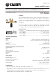
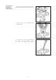
Install Instructions
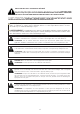
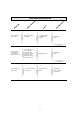

Maintenance
Since the backflow preventer valve is used to ensure the safety of domestic water supplies it must
be inspected per local codes. The first sign that the equipment is not functioning properly, generally
associated with the presence of sand or other impurities is indicated by a permanent leakage through
the discharge. This loss is just an initial warning sign and does not completely jeopardize the safety
of the check mechanism but means that the unit should be dismantled and the equipment should be
cleaned. A rapid inspection method, which should take less than 15 minutes is described in the table
below.
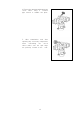
In the event of dripping at the discharge it is recommended to create strong circulation flow for a few
minutes by opening one or more taps. This is usually sufficient to flush out any sand or other impurities
to restore normal operation.
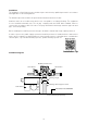
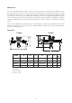
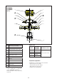
Dimensions
A
D
E
B
C
A
D
E
F
B
C
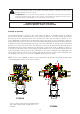
A
adjustment screw
Code A B C D E F
Wt
(lb)
574004A ½" FNPT 3¼” 6¼” 40 mm 9¾” --- 5.0
574064A ½" press* 3¼” 6¼” 40 mm 12
3
/8" --- 5.1
574050A ¾" FNPT 4" 10½” 40-60 mm 13¼” 1¾” 9.5
574056A ¾" press* 4" 10½” 40-60 mm 16½” 1¾” 9.6
5
½ inch
¾ inch
*Laylength:
½" press: 10
7
/8".
¾" press: 14½".