
Brochure


84
6
C
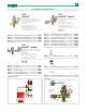
BACKFLOW PREVENTERS, DUAL CHECK, FOR PLUMBING AND HYDRONICS
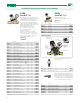
Testable reduced pressure zone backflow
preventer.
DZR low lead brass body.
Max. working pressure: 150 psi.
Max. working temperature: 150°F.
574
RPZ Backflow Preventer
Code Description Lbs USD
574004A ½" FNPT 5.0
520.00
574064A ½" press 5.1 551.00
59977 Replacement upstream check valve 0.1 32.30
59978 Replacement discharge valve assembly 0.2 57.80
59979 Replacement downstream check valve 0.1 37.30
59980 Replacement discharge air gap 0.1 14.00
Testable reduced pressure zone backflow
preventer.
DZR low lead brass body.
Max. working pressure: 150 psi.
Max. working temperature: 150°F.
574
RPZ Backflow Preventer
Code Description Lbs USD
574050A ¾" FNPT 9.5 624.00
574056A ¾" press 9.6 676.00
59469 Replacement upstream check valve 0.2 83.20
59470 Replacement downstream check valve 0.2 88.10
59471 Replacement discharge valve assembly 0.3 175.00
59472 Replacement valve seat 0.1 62.30
39623 Replacement discharge air gap 0.2 20.70
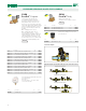
Dual check continuous pressure backflow
preventer with atmospheric vent.
DZR low Lead brass body.
Max. working pressure: 175 psi.
Working temperature range: 32—250°F.
Emergency backpressure temperature: 250°F
Certified to: ASSE 1012, CSA B64.3, NSF 372, Low Lead Laws and listed
by ICC-ES. Meets codes IPC, IRC & UPC for use in accordance with the
U.S. and Canadian plumbing codes.
573
Dual Check Backflow Preventer
ASSE 1012
Code Description Lbs USD
573403A ½" NPT female unions 1.7 134.00
573406A ½" press unions 1.7 163.00
573409A ½" sweat unions 1.7 128.00
573493A ½" sweat union inlet, ½" FNPT union outlet 1.7 131.00
573503A ¾" NPT female unions 1.7 141.00
573100A* Replacement body w/washers 1.5 98.80
ASSE 1013
ASSE 1013
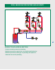
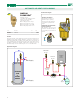
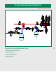
Construction details
BACKFLOW PREVENTERS, RPZ TYPE, FOR PLUMBING AND HYDRONICS
The testable reduced pressure zone
backflow preventer is composed of a
body with a removable cover, upstream
and downstream check valves and
relief valve. The two check valves
create three separate pressure zones:
upstream or inlet zone; intermediate,
also known as the reduced pressure
zone; and a downstream, or outlet
zone. Each has a test port to measure
pressure. A relief valve is located in
the lower part of the reduced pressure
zone. The valve stem of the relief valve
is connected to the diaphragm, and
is forced upward by the spring. The
diaphragm separates the water in
the upstream zone of the operation
chamber from the water in the reduced
pressure zone (RPZ) chamber.
NEW
NEW
*See fitting selection table in Section 8
Certified to: ASSE 1013, CSA B64.4, NSF372, Low Lead Laws and listed by ICC-ES. Meets codes IPC, IRC & UPC for use in accordance with the U.S. and
Canadian plumbing codes.
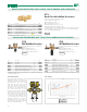
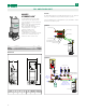
Flow capacity
0
5
10
15
20
25
0 5 10 15 20 25 30 35 40
PRESSURE LOSS (PSI)
FLOW RATE (GPM)
(3/4 inch)
574050A
574056A
(1/2 inch)
574004A
574064A
(kPa)
35
70
100
140
170
(LPM)
20 40 60 80 100
||||| |
120
|
140
Size Max. Cv
1/2 inch 3.4
3/4 inch 7.8