
Brochure


1213121
8
101
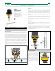
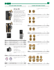
Universal flow switch.
Suitable for 1" to 8" pipe size.
Working pressure: 150 psi.
Working temperature range: -20 – 250°F.
Minimum flow: 5.7 gpm.
Switch contacts: NO or NC
Switch rating: 15 A
CE, cUL, NEMA Type 5, IP 54.
626
Uni-Switch
TM
Code Description Lbs USD
626600A
1" NPT male thread
2.3 361.00
626009 Replacement paddle assembly* 0.1 33.80
* stainless steel
UNIVERSAL FLOW SWITCH
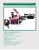
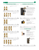
Operating principle
The flow switch is composed of a paddle (blade) (1) integral with a control
rod (2) connected, at the top, to an adjustable counter spring (3). The
assembly, by turning around a pin under the action of the water flow,
operates a microswitch contained in a protective casing (4). At rest, the
counter spring keeps the microswitch contact open. When the increasing
flow rate of the medium within the piping becomes equal or greater
than the trip flow rate, the thrust (5) on the blade applied (1) by the flow
overcomes the opposing force applied by the adjustable counter spring (3)
thus making the microswitch contact close. With a decreasing flow rate,
on reaching the trip flow rate values, the flow thrust on the blade is not
enough to overcome the opposing force applied by the adjustable spring,
so the blade returns to the rest position and the microswitch contact
opens.
The trip values for closing (increasing flow) and opening (decreasing flow)
the microswitch contact can be modified with the adjusting screw (6).
5
3
4
2
1
8
7
6
8
Function
The flow switch detects whether there is any flow in the piping and
opens or closes an electrical contact. It is normally used in heating,
air-conditioning, refrigeration, water treatment, additive pumping and
process systems in general. The flow switch can control devices such
as pumps, burners, compressors, refrigerators, motorized valves; to turn
on indicator and alarm devices and regulate equipment for dosing water
additives.
In heating systems, the flow switch will switch the burner off in case of a
lack of fluid circulation in heating circuit. A lack of fluid circulation would
otherwise impair the operation of the temperature-sensitive safety and
protection devices.
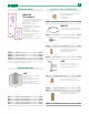
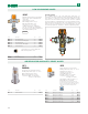
Installation
The unit is equipped with a set of paddles (blades) (1), to be used for
different pipe diameters, particularly sized to allow easy installation and
minimal head losses.
For diameters equal to or greater than 3” (DN 80), it is necessary to add
to the preassembled blades in increasing order on the long blade (2)
(supplied in the package), just cutting it to the size corresponding to the
desired diameter. Replacement paddle or blade assemblies are available,
order part number 626009.
8"
1-1/2"
1”
1-1/4”
2"
2-1/2”
6"
5"
4"
3"
DN175
1
2
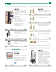
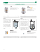
Flow rate adjustment
Adjustments should be carried
out as follows: turn the adjusting
screw (1) in a clockwise direction
for the contacts to close at higher
flow rates or in a counterclockwise
direction for lower flow rates.
When the adjustment has been
made, lock the screw (A) with
the locking ring nut (2). Avoid all
contact with the presetting screw
(3). An incorrect setting would
seriously impair the operation of
the switch.
1
2
3