
Overview of Primary Product

Max amount in gallons of dissolved air per 100 gallons of water
0
0.5
1.0
1.5
2.0
2.5
3.0
3.5
4.0
4.5
5.0
5.5
15 psi
30 psi
45 psi 60 psi 75 psi 90 psi 105 psi 120 psi
Absolute pressure
32 65 100 135 170 205 240 275 310 345
2
1
3
2
1
3
2
1
A
B
3
2
1
3
4
4
4
4
3
2
1
4
2
1
3
2
1
3
2
1
A
B
3
2
1
3
4
4
4
4
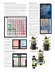
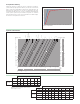
The process of air formation
The amount of air which can remain dissolved in a water solution is
a function of pressure and temperature. This relationship is governed
by Henry’s Law and the graph below demonstrates the physical
phenomenon of the air release from water. As an example, at a constant
absolute pressure of 30 psi (2 bar), if the water is heated from 65ºF
(18ºC) to 170ºF (75ºC), the amount of air released by the solution is equal
to 1.8 gallons of air per 100 gallons ofwater. According to this law it can
be seen that the amount of air released increases with temperature rise
and pressure reduction. The air comes in the form of micro-bubbles of
diameters in the order of tenths of amillimeter.
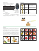
In heating and cooling systems there are specific points where this
process of formation of micro-bubbles takes place continuously: in the
boiler and in any device which operates under conditions of cavitation.
Boiler micro-bubbles
Micro-bubbles are
formed continuously
on the surface
separating the water
from the combustion
chamber due to the
fluid temperature.
This air, carried by the
water, collects in the
critical points of the
circuit from where it
must be removed.
Some of this air is reabsorbed in the presence of colder surfaces.
Cavitation and micro-bubbles
Micro-bubbles
develop where
the fluid velocity
is very high with
the corresponding
reduction in pressure.
These points are
typically the pump
impeller and the
valveport.
These air and vapor
micro-bubbles, the
formation of which is
enhanced in the case
of non de-aerated
water, may subsequently implode due to the cavitation phenomenon.
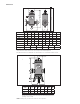
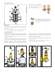
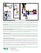
Operating principles
The DISCAL air separator is
used to continuously remove the
air contained in hydronic circuits
of heating and cooling systems.
The air discharge capacity is
very high. They are capable of
removing automatically all the air
present in the system down to
micro-bubble level with low head
loss due the special internal
shape of the separator body.
Flow direction of the DISCAL air
separator is bidirectional; flow in
either direction is permitted.
The air separator uses the
combined action of several
physical principles. The active
part consists of an assembly
of concentric mesh surfaces
(1). These elements create the
whirling movement required to
facilitate the release of micro-
bubbles and their adhesion to
these surfaces.
The bubbles, fusing with each
other, increase in size until the
hydrostatic thrust overcomes
the adhesion force to the mesh.
They rise towards the top of the
unit from which they are released
through a float-operated (2)
automatic air vent, with stainless
steel float guide pin (3) and stainless steel float linkages (4).
Combustion chamber
wall
Boundary layer
Average water
temperature
Boundary layer
temperature
FLAME WATER
Micro-bubbles
Flame temperature
Wall temperature
Pressure
Velocity
Cavitation
micro-bubbles
Pressure Velocity
Implosions
Valve port
Fluid vapor
pressure
1
2
3
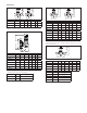
551 compact series
5517 rotating collar series
551 brass series