
Submittal Sheet
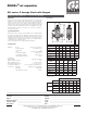

DISCAL
®
air separator
551 series, 2 through 6 inch with flanges
CALEFFI
Application
Air separators are used to continuously remove the air contained in
hydronic circuits of heating and cooling systems. The air discharge
capacity of these devices is very high. They automatically remove
all the air present in the system down to micro-bubble level with low
head loss due to the special internal shape of the separator body. The
circulation of fully de-aerated water enables the equipment to operate
under optimum conditions, free from noise, corrosion, localized or
mechanical damage.
Submittal Data 2906 NA — Issue Date 10/2018
Dimensions
Typical Specication
Furnish and install on the plans and described herein, a Caleffi DISCAL
®
air separator as manufactured by Caleffi. Each separator must be designed
with a blowdown drain port, side drain valve and automatic air vent. The
separator design must include a 304 stainless steel coalescing medium to
automatically remove all air present in the system. Each separator shall be
a Caleffi model 551 or approved equal.
(See product instructions for specific installation information.)
Technical data
Materials - body: epoxy resin coated steel
- internal element: 304 stainless steel
- air vent float: PP
- seal: peroxide-cured EPDM
- air vent float linkages: stainless steel
- air vent float guide pin: stainless steel
- side drain shut-off valve: brass
Performance
Suitable fluids: water, glycol solution
Max. percentage of glycol: 50%
Max. working pressure: 150 psi (10 bar)
Temperature range (vessel): 32–270°F (0–132°C)
Air separation efficiency: 100% removal to microbubble level
Connections - flanged: ANSI B16.5 150 CLASS RF
- drain pipe: 1" NPT male
- side drain shut-off valve: ¾" GHT
D
B
E
A
A
A
D
B
E
A
A
D
B
E
A
F
F J
C
B
A
H
D
E
F F
A
D
B
E
F
A
F
T
max
250ϒF
P
max 150 psi
T
max
220ϒF
P
max 150 psi
BI-DIRECTIONAL
38466.01
A
A
D
E
C C C
C C
G
B
G
WALL
Code A B C D E F
551050A 2" 13
3
⁄4" 1" 14
3
⁄4" 19
15
⁄16" 6
5
⁄8"
551060A 2
1
⁄2" 13
3
⁄4" 1" 14
3
⁄4" 19
15
⁄16" 6
5
⁄8"
551080A 3" 18
3
⁄8" 1" 17
1
⁄8" 23
7
⁄16" 8
5
⁄8"
551100A 4" 18
1
⁄2" 1" 17
1
⁄8" 23
7
⁄16" 8
5
⁄8"
551120A 5" 25" 1" 21
7
⁄16" 30
1
⁄2" 12
3
⁄4"
551150A 6" 25" 1" 21
7
⁄16" 30
1
⁄2" 12
3
⁄4"
Code G H J
†
Cap
(gal)
Wt (lb)
551050A 2
13
⁄16" 6" 6
5
⁄16" 1.8 34
551060A 2
13
⁄16" 7" 6
5
⁄16" 1.8 35
551080A 2
13
⁄16" 7
1
⁄2" 7
5
⁄16" 4.8 62
551100A 2
13
⁄16" 9" 7
5
⁄16" 4.8 67
551120A 2
13
⁄16" 10" 9
3
⁄8" 13.7 106
551150A 2
13
⁄16" 10" 9
3
⁄8" 13.7 117
Flow capacity — steel
Size 2" 2 ½" 3" 4" 5" 6"
4.0 f/s
GPM 39 60 90 160 245 355
l/s 2.5 3.8 5.7 10 15.5 22.4
10.0 f/s
GPM 100 155 220 400 615 880
l/s 6.3 9.8 14 25.2 38.8 55.5
Cv 87 174 208 324 520 832
†
This dimension allows for a minimum of 3" wall clearance to accommodate
insulation if used.
We reserve the right to change our products and their relevant technical data, contained in this publication, at any time and without prior notice. Contractors should request production drawings if prefabricating the system
.
Job name ______________________________________
Job location ______________________________________
Engineer ______________________________________
Mechanical contractor ________________________________
Contractor’s P.O. No. ________________________________
Representative ________________________________
Size ________________________________________
Quantity ________________________________________
Approval ________________________________________
Service ________________________________________
Tag No. ________________________________________
Notes ________________________________________
Calef North America, Inc. 3883 W. Milwaukee Road / Milwaukee, WI 53208
Tel: 414-238-2360 / Fax: 414-238-2366 / www.calef.com
© Copyright 2018 Calef North America, Inc.