
Submittal Sheet

CALEFFI
Application
Air separators are used to continuously remove the air contained
in thehydronic circuits of heating and cooling systems. The air
dischargecapacity of these devices is very high. They are capable of
removing automatically all the air present in the system down to the
micro-bubble level.
The circulation of fully de-aerated water enables the equipment to
operate under optimum conditions, free from noise, corrosion, localized
or mechanical damage. Micro-bubbles, fusing with each other, increase
in volume (get larger) until they become large enough to rise to the top
where they are automatically released.
Submittal Data 02904 NA — Issue Date 10/2018
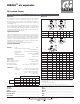
Dimensions
Typical Specification
Furnish and install on the plans and described herein, a Caleffi DISCAL
®
Air
Separator as manufactured by Caleffi. Each separator must be designed
with a brass valve body and seals in peroxide-cured EPDM. The separator
design must include a removable internal glass-reinforced nylon fiber mesh
- PA66G30, coalescing medium (304 stainless steel for compact version), to
automatically remove all air present in the system. Each separator shall be
Caleffi model 551 or approved equal.
(See product instructions for specific installation information.)
We reserve the right to change our products and their relevant technical data, contained in this publication, at any time and without prior notice. Contractors should request production drawings if prefabricating the system
.
Job name ______________________________________
Job location ______________________________________
Engineer ______________________________________
Mechanical contractor ________________________________
Contractor’s P.O. No. ________________________________
Representative ________________________________
Size ________________________________________
Quantity ________________________________________
Approval ________________________________________
Service ________________________________________
Tag No. ________________________________________
Notes ________________________________________
Technical specification
Materials - body: brass
- internal element (compact version):
304 stainless steel
- internal element: glass reinforced nylon PA66GF30
- air vent float: PP
- seal: peroxide-cured EPDM
- air vent float linkages: stainless steel
- air vent float guide pin: stainless steel
Performance
Suitable fluids: water, glycol solution
Max. percentage of glycol: 50%
Max. working pressure: 150 psi (10 bar)
Temperature range: 32–250°F (0–120°C)
Air separation efficiency: 100% removal to micro-bubble level
Connections - main:
compact series: ¾" integral sweat; ¾" NPT female
horizontal: ¾", 1", 1¼", 1½" and 2" NPT female
1", 1¼", 1½ " and 2" integral sweat
1", 1¼", 1½ " and 2" integral press
- drain: ½" NPT female
2018
com
DISCAL
®
air separator
551 series, brass
D
B
E
A
A
A
D
B
E
A
A
D
B
E
A
F
G
F
B
A
D
E
F F
A
D
B
E
F
A
G
F
B
A
D
E
T
max
250F
P
max 150 psi
T
max
220F
P
max 150 psi
BI-DIRECTIONAL
38466.01
T
max
250F
P
max 150 psi
T
max
220F
P
max 150 psi
BI-DIRECTIONAL
38466.01
A
A
D
E
C
C
C
C C
C C
B
G
A
D
B
E
A
F
C
Code A B C D E F Wt (lb)
551003A*
3
⁄4" NPT 3
1
⁄16" 2
3
⁄16" 5
3
⁄8" 6
7
⁄8"
1
⁄2" 2.0
551022A*
3
⁄4" SWT 3
1
⁄16" 2
3
⁄16" 5
3
⁄8" 6
7
⁄8"
1
⁄2" 2.0
D
B
E
A
A
A
D
B
E
A
A
D
B
E
A
F
G
F
B
A
D
E
F F
A
D
B
E
F
A
G
F
B
A
D
E
T
max
250F
P
max 150 psi
T
max
220F
P
max 150 psi
BI-DIRECTIONAL
38466.01
T
max
250F
P
max 150 psi
T
max
220F
P
max 150 psi
BI-DIRECTIONAL
38466.01
A
A
D
E
C
C
C
C C
C C
B
G
A
D
B
E
A
F
C
* Add suffix C to sweat, NPT and press code numbers when ordering
the brass DISCAL to ship with expansion tank service check valve,
code561402A.
Press connection lay length:
size 1": 4
1
⁄2" ; size 1¼": 5
1
⁄8"; size 1
1
⁄2": 5
1
⁄4": size 2": 5
1
⁄2".
Code A B C D E F Wt (lb)
551005A*
3
⁄4" NPT 4
5
⁄16" 2
3
⁄16" 5
3
⁄4" 7
1
⁄2"
1
⁄2" 3.7
551006A* 1" NPT 4
5
⁄16" 2
3
⁄16" 5
3
⁄4" 7
1
⁄2"
1
⁄2" 3.7
551007A* 1
1
⁄4" NPT 4
7
⁄8" 2
3
⁄16" 6
9
⁄16" 8
1
⁄4"
1
⁄2" 4.9
551008A* 1
1
⁄2" NPT 4
7
⁄8" 2
3
⁄16" 6
9
⁄16" 8
1
⁄4"
1
⁄2" 4.9
551009A* 2" NPT
5
1
⁄8" 2
3
⁄16" 6
9
⁄16" 8
1
⁄4"
1
⁄2" 5.5
551028A* 1" SWT 5
1
⁄16" 2
3
⁄16" 5
3
⁄4" 7
1
⁄2"
1
⁄2" 3.7
551035A* 1
1
⁄4" SWT 5
3
⁄16" 2
3
⁄16" 6
5
⁄16" 8
1
⁄4"
1
⁄2" 3.7
551041A* 1
1
⁄2" SWT 5
3
⁄4" 2
3
⁄16" 6
9
⁄16" 8
1
⁄4"
1
⁄2" 4.9
551054A* 2" SWT 6
1
⁄8" 2
3
⁄16" 6
9
⁄16" 8
1
⁄4"
1
⁄2" 5.5
551066A* 1" press 6
3
⁄16" 2
3
⁄16" 5
3
⁄4" 7
1
⁄2"
1
⁄2" 3.8
551067A* 1¼" press 7
7
⁄16" 2
3
⁄16" 5
3
⁄4" 7
1
⁄2"
1
⁄2" 5.0
551068A* 1
1
⁄2" press 8" 2
3
⁄16" 6
9
⁄16" 8
1
⁄4"
1
⁄2" 5.1
551069A* 2" press 8
1
⁄2" 2
3
⁄16" 6
9
⁄16" 8
1
⁄4"
1
⁄2" 5.5
Flow capacity
Size ¾" C ¾" 1" 1¼" 1½" 2"
4.0 f/s
GPM 6 6 10 15 22 39
l/s 0.4 0.4 0.6 1.0 1.4 2.5
Cv 12 19 32 56 73 81