
Brochure
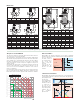

The process of air formation
The amount of air which can remain dissolved in a water solution is
a function of pressure and temperature.
This relationship is governed by Henry’s Law and the graph below
demonstrates the physical phenomenon of the air release from water.
As an example, at a constant absolute pressure of 30 psi (2 bar), if
the water is heated from 65°F (18°C) to 170°F (75°C), the amount
of air released by the solution is equal to 1.8 gallons of air per 100
gallons of water.
According to this law it can be seen that the amount of air released
increases with temperature rise and pressure reduction. The air
comes in the form of micro-bubbles of diameters in the order of
tenths of a millimeter.
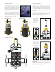
In heating and cooling systems there are specific points where this
process of formation of micro-bubbles takes place continuously: in the
boiler and in any device which operates under conditions of cavitation.
Boiler micro-bubbles
Micro-bubbles are formed continuously on the surface separating
the water from the combustion chamber due to the fluid temperature.
This air, carried by
the water, collects
in
the critical points
of
the circuit from
where it must be
removed.
Some of this air is
reabsorbed in the
presence of colder
surfaces.
Cavitation and micro-bubbles
Micro-bubbles develop where the fluid velocity is very high with the
corresponding reduction in pressure.These points are typically the
pump impeller and
the valve port.
These air and vapor
micro-bubbles, the
formation of which
is enhanced in
the case of non
de-aerated water,
may subsequently
implode due to
the cavitation
phenomenon.
Max amount in gallons of dissolved air per 100 gallons of water
0
0.5
1.0
1.5
2.0
2.5
3.0
3.5
4.0
4.5
5.0
5.5
15 psi
30 psi
45 psi 60 psi 75 psi 90 psi 105 psi 120 psi
Absolute pressure
Water temperature
32 65 100 135 170 205 240 275 310 345
Combustion chamber
wall
Boundary layer
Average water
temperature
Boundary layer
temperature
FLAME WATER
Micro-bubbles
Flame temperature
Wall temperature
Pressure
Velocity
Cavitation
micro-bubbles
Pressure Velocity
Implosions
Valve port
Fluid vapor
pressure
A
3/4”
3/4” swt
B
3
1/16”
3
1/16”
C
B
D
A
A
A
C
B
D
A
A
C
B
D
A
E
F
E
B
A
C
D
A
2”
2
1/2”
3”
4”
5”
6”
2”
2
1/2”
3”
4”
B
13
3/4”
13
3/4”
18
3/8”
18
1/2”
25
25
10
1/4”
10
1/4”
14
5/8”
14
5/8”
Weight (lb)
33.1
34.2
61.7
66.1
105.8
116.8
20.5
21.0
44.0
46.3
C
14
3/4”
14
3/4”
17
1/8”
17
1/8”
21
7/16”
21
7/16”
14
3/4”
14
3/4”
17
1/8”
17
1/8”
D
19
15/16”
19
15/16”
23
7/16”
23
7/16”
30
1/2”
30
1/2”
19
15/16”
19
15/16”
23
7/16”
23
7/16”
F
6
5/8”
6
5/8”
8
5/8”
8
5/8”
12
3/4”
12
3/4”
6
5/8”
6
5/8”
8
5/8”
8
5/8”
E
1"
1"
1"
1"
1"
1"
1"
1"
1"
1"
Code
551022A
551003A
Code
551005A*
551006A*
551007A*
551008A*
551009A*
551028A*
551035A*
551041A*
551054A*
Code
**551050A
**551060A
**551080A
**551100A
**551120A
**551150A
NA551050T
NA551060T
NA551080T
NA551100T
Weight (lb)
2.0
2.0
Size
Cap. (gal)
2”
1.8
2 1/2”
1.8
3”
4.8
4”
4.8
5”
13.7
6”
13.7
C
5
5/8”
5
5/8”
D
6
7/8”
6
7/8”
A
3/4”
1”
1
1/4”
1
1/2”
2”
1” swt
1
1/4” swt
1
1/2” swt
2” swt
B
4
5/16”
4
5/16”
4
7/8”
4
7/8”
5
1/8”
5
1/16”
5
3/16”
5
3/4”
6
1/8”
Weight
(lb)
3.7
3.7
4.9
4.9
4.9
3.7
3.7
4.9
5.5
C
5
3/4”
5
3/4”
6
9/16”
6
9/16”
6
9/16”
5
3/4”
6
5/16”
6
9/16”
6
9/16”
D
7
1/2”
7
1/2”
8
1/4”
8
1/4”
8
1/4”
7
1/2”
8
1/4”
8
1/4”
8
1/4”
E
1/2”
1/2”
1/2”
1/2”
1/2”
1/2”
1/2”
1/2”
1/2”
E E
E
1/2”
1/2”
A
C
B
D
E
A
F
E
B
A
C
D
Tmax 250∞F
P
max 150 psi
Tmax 220∞F
P
max 150 psi
BI-DIRECTIONAL
38466.01
Tmax 250∞F
P
max 150 psi
Tmax 220∞F
P
max 150 psi
BI-DIRECTIONAL
38466.01
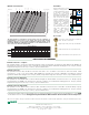
Dimensions
* Add suffix C to sweat and NPT code number when ordering the Brass Discal to ship with expansion tank check valve, code 561402A.
** Add prefix NA to flanged code number when ordering ASME tagged and registered with the National Board of Boiler and Pressure Vessel Inspector