
Submittal Sheet
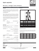

Hydro separator
548 series, 1" through 2" union connections
CALEFFI
Application
The hydraulic separator creates a zone with a low pressure loss, which
enables connected primary and secondary circuits to be hydraulically
independent of each other; the flow in one circuit does not create or
interupt flow in another. Hydraulically decoupling primary and secondary
circuits eliminates pump conflict.
Submittal Data 2909 NA — Issue Date 10/2018
Dimensions
Typical Specication
Furnish and install on the plans and described herein, a Caleffi Hydro
Separator
as manufactured by Caleffi. Each separator must be designed
with an epoxy resin painted steel body, 300 series stainless steel internal
baffle, preformed insulation, a ½" threaded thermometer pocket well front
center, a brass blowdown valve with garden hose connection and automatic
brass air vent isolated manually with service check valve. The separator
design must include sweat, press or NPT female connections with cast iron
union nuts. Each separator shall be a Caleffi model 548 series or approved
equal. (See product instructions for specific installation information.)
Technical data
Materials - body: epoxy resin painted steel
- internal baffle: 300 series stainless steel
- air vent body: brass
- shut off and drain valve body: brass
- union nuts: cast iron
Performance
Suitable fluids: water and non-hazardous glycol solution up to 50%
Max. operating pressure: 150 psi (10 bar)
Working temperature range with insulation: 32–210°F (0–100°C)
Working temperature range without insulation: 32–250°F (0–120°C)
Connections - main: 1",1-¼",1-½", 2" NPT female with unions
1",1-¼",1-½", 2" sweat with unions
1",1-¼",1-½", 2" press with unions
- thermo well tap: ½" straight thread female
- lay length (press connections): size 1 inch : 9"
size 1-¼ inch: 9-¾"
size 1-½ inch: 11-¼"
size 2 inch: 12-¾"
- drain valve: ¾" garden hose thread
Technical specications of insulation
Materials: double density closed cell expanded PEX
Thickness: ¾" (20 mm)
Density: - internal part:
2 lb/ft
3
(
30 kg/m
3
)
- external part: 3.1 lb/ft
3
(50 kg/m
3
)
Thermal conductivity: 32°F (0°C): 9 BTU
.
in/hr
.
ft
2
.
°F (0.038 W/(m
.
K)
-40°F (-40°C): 11 BTU
.
in/hr
.
ft
2
.
°F (0.045 W/(m
.
K)
Coefficient of resistance to the diffusion of vapor: >1,300
Temperature range: 32–210°F (0–100°C)
Reaction to fire (DIN4102): class B2
A
1
”
1
1/4”
1
1/2”
2”
B
8
3/4”
9
3/8”
10
7/8”
12”
C
6
1/4”
7
3/8”
7
3/4”
10
1/8”
Code
548052A
548062A
548082A
548102A
NA548120A*
NA548150A*
Code
548
006A/96A
548
007A/97A
548
008A/98A
548
009A/99A
Weight (lb)
13
17
25
27
D EC
B
A
A
T
max
120C
P
max
10 bar
T
max
105C
P
max
10 bar
A
8
”
10
”
12
”
Code
NA548200A
NA548250A
NA548300A
B
1¼”
= drain valve size
C D E
A
HYDRO SEPARATOR
Serie 548
T
max
120C
P
max
10 bar
T
max
105C
P
max
10 bar
A
HYDRO SEPARATOR
D
8
5/8”
9
1/2”
10
1/4”
11
7/8”
E
8”
8
3/8”
8
3/4”
9
1/2”
Flow (gpm)
11
18
26
37
Vol. (gal)
0.5
0.7
1.3
3.5
A
2
”
2
1/2”
3
”
4”
5”
6”
B
1
1/4”
1
1/4”
1
1/4”
1
1/4”
1
1/4”
1
1/4”
C
13
”
13
”
15
”
15
”
15
”
15
”
D
13
”
13
”
18
”
18
”
22
”
22
”
E
15
”
15
”
17
”
17
”
19
”
19
”
F
14
”
14
”
18
”
18
”
25
”
25
”
Weight (lb)
75
82
112
117
220
231
Flow (gpm)
60
80
124
247
300
484
Vol. (gal)
4.0
4.0
8.0
8.0
22.5
23.2
B
C D E
A A
B
2
”
2
”
2
”
C
39
3/8”
43
5/16”
47
1/4”
D
33
7/8”
35
7/8”
37
7/8”
E
27
1/2”
30”
31
1/2”
F
35
1/2”
41
3/4”
47
3/4”
Weight (lb)
520
725
1,100
Flow (gpm)
792
1,330
1,850
Vol. (gal)
95
175
255
HYDRO-SEPARATOR
Serie 548
T
max
110C P
max
10 bar
38...
2”
= drain valve size
F
F
F
We reserve the right to change our products and their relevant technical data, contained in this publication, at any time and without prior notice. Contractors should request production drawings if prefabricating the system
.
Job name ______________________________________
Job location ______________________________________
Engineer ______________________________________
Mechanical contractor ________________________________
Contractor’s P.O. No. ________________________________
Representative ________________________________
Size ________________________________________
Quantity ________________________________________
Approval ________________________________________
Service ________________________________________
Tag No. ________________________________________
Notes ________________________________________
Calef North America, Inc. 3883 W. Milwaukee Road / Milwaukee, WI 53208
Tel: 414-238-2360 / Fax: 414-238-2366 / www.calef.com
© Copyright 2018 Calef North America, Inc.
Code* A
B
swt/
press
B
fnpt
C D E F
Wt.
(lbs.)
Wt.
(kg)
548006A/96A
1" 8
3
⁄4" 8
1
⁄2" 7" 8
5
⁄8" 8
1
⁄2" 3" 13 6.0
548007A/97A
1
1
⁄4" 9
1
⁄2" 9" 8
1
⁄2" 9
1
⁄2" 8
1
⁄2" 3½" 17 7.7
548008A/98A
1
1
⁄2" 11 " 10
1
⁄2" 8
1
⁄2" 10
1
⁄4" 9
1
⁄4" 4½" 25 11.3
548009A/99A
2" 12
3
⁄8" 11
1
⁄2" 9
1
⁄2" 11
7
⁄8" 9
1
⁄4" 5¾" 27 12.2
548066A
1" 10
3
⁄4" -- 7" 8
5
⁄8" 8
1
⁄2" 3" 13 6.0
548067A
1
1
⁄4" 11
3
⁄4" -- 8
1
⁄2" 9
1
⁄2" 8
1
⁄2" 3½" 17 7.7
548068A
1
1
⁄2" 14" -- 8
1
⁄2" 10
1
⁄4" 9
1
⁄4" 4½" 25 11.3
548069A
2" 15
3
⁄4" -- 9
1
⁄2" 11
7
⁄8" 9
1
⁄4" 5¾" 27 12.2
* 54800: NPT female union connections; 54809: sweat union connnections; 54806: press
union connections.
Hydraulic characteristics
The hydraulic separator should be sized according to the maximum
flow rate value at the inlet.The selected design value must be the greatest
required flow rate of either the primary circuit or the secondary circuit.
Union connections
Size 1" 1
1
/4" 1
1
/2" 2"
gpm
11 18 26 37
l/s 0.7 1.1 1.6 2.3
gallons
0.5 0.7 1.3 3.5
liters
1.9 2.6 4.9 13.2