
Install Instructions
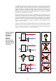

1
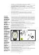
. Demonteer de voorgeassambleerde isolatie door de bodemkap (A) van de
vuilopvangkamer af te halen en vervolgens het bovendeel (B) te verwijderen.
2
. Indien het noodzakelijk wordt om te spuien, verwijder ring (c) die 2 magneten bevat die
de ijzerhoudende vuildeeltjes verzamelen en vasthoudt.
N
B. werkwijze ook geldig voor de verticale vuilafscheiders serie 5468 zonder isolatie.
3. Vervolgens kan men het opgevangen vuil verwijderen door de bedieningshendel van de
spuikraan te openen.
4. Wanneer al het vuil verwijderd is, sluit de spuikraan en plaats de ring (C) en isolatieschalen
(A) en (B) terug zoals omgeschreven in punt 1 en 2.
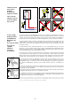
1. Öncelikle toplama haznesinin alt tarafını (A) ve ardından eğer gerekiyorsa üst tarafını (B) çıkartarak
ö
nceden takılmış yalıtımı çıkartın.
2. Kir ayırma aşamasında demir esaslı parçacıkları tutan iki mıknatısı içeren halkayı (C) çıkartın.
NB: Bu işlem ayrıca 5468 serisi yalıtımsız dikey tortu tutucular için de geçerlidir.
3. Özel anahtarlı (E) küresel kesme vanasını (D) açarak tortu boşaltma işlemini gerçekleştirin.
4
. Tortu boşaltma işlemi tamamlandıktan sonra, 1. ve 2. noktalarda gösterilen prosedürü baştan sona
izleyerek yalıtımı yeniden takın.
9
Procedura di
installazione
di assemblaggio
coibentazione e
rimozione magnete
serie 5465 e 5466
DN 50÷DN 150.
Procedure for
installation
insulation assembly
and magnet
extraction
5465 e 5466 series
DN 50–DN 150.
Installation und
Montage der
Isolierung und
Magnetentnahme
Serie 5465 und 5466
DN 50
÷
DN 150.
Procédure
d'installation de la
coqued'isolation et
dépose de l'aimant
série 5465 et 5466
DN 50
÷
DN 150.
Procedimiento de
instalación,
ensamblaje del
aislamiento y
extracción del imán
series 5465 y 5466
DN 50
÷
DN 150.
Procedimento de
instalação /
montagem do
isolamento e
remoção do íman
série 5465 e 5466
DN 50-DN 150.
Plaatsing
isolatieschalen en
verwijdering
magneet
serie 5465 en 5466
DN 50
÷
DN 150.
Tesisat yalıtımı
montajı ve mıknatıs
çıkartma prosedürü,
5465 ve 5466 serileri
DN 50-DN 150.
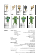
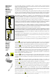
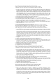
1. Per la serie 5466, prima di rimuovere la coibentazione occorre svitare il magnete, agendo
sull’apposita manopola, ed estrarlo dal pozzetto. Per le misure DN 50 e DN 65 il magnete è
composto da due pezzi, mentre per il range DN 80÷DN 150 il magnete è composto da tre
pezzi. In questo modo l’estrazione del magnete è agevolata, in quanto è possibile spezzarlo
in più parti durante l’operazione, consentendo inoltre di limitare gli spazi necessari sotto al
defangatore per effettuare tale procedura. Si raccomanda di maneggiare il magnete con
attenzione: l’elevato campo magnetico attrae gli spezzoni con forza, rischio di
schiacciamento delle dita.
2. Sfilare le due coperture di testa nere alle estremità*.
3. Aprire il tappo superiore (per misure fino a DN 100) e i due gusci laterali.
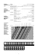
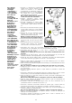
4.
Procedere all’installazione del defangatore sull’impianto.
5. Per le misure fino a DN 100 stendere sulle superfici A e B un leggero strato di sigillante e
attendere che il solvente sia evaporato. Per le restanti misure DN 125 e DN 150 togliere la
pellicola dell’adesivo già applicato sulle superfici.
6. Incastrare il tappo superiore su uno dei due gusci e unire successivamente l’altro*.
7. Riassemblare i due gusci laterali.
8. Rifinire la giunzione con la striscia in dotazione nella scatola.
9. Completare con le due coperture di testa nere*.
10. Per la serie 5466, inserire nuovamente il magnete ed avvitare a battuta.
N.B.: Sigillante consigliato: Mastice Superchiaro ns. cod. 615500.
*Operazioni da non eseguire per i defangatori DN 125 e DN 150.
1. For 5466 series, before removing the insulation it is necessary to unscrew the magnet, by
acting on the specific knob, and extract it from the pocket. For sizes DN 50 and DN 65 the
magnet is composed of two pieces, while for the range DN 80÷DN 150 the magnet is
composed of three pieces. In this way the magnet extraction is facilitated, since it is possible
to split it into several parts during the operation. Furthermore, this allows to reduce the
necessary space underneath the dirt separator to perform this procedure. It is
recommended to pay attention while handling the magnet: the strong magnetic field attracts
the magnet parts with strength therefore with the risk of squeezing fingers.
2. Extract the black head covers at the two ends*.
3. Open the upper cap (for sizes up to DN 100) and the two side shells.
4. Install the dirt separator on the system.
5. For sizes up to DN 100 spread a light layer of sealant onto the surfaces A and B and wait for
the solvent to evaporate. For the remaining sizes DN 125 and DN 150 peel off the film of
adhesive already applied on the surfaces.
6. Fit the upper cap onto one of the two shells and then join on the other one*.
7. Reassemble the two side shells.
8. Finish the join with the strip provided in the box.
9. Complete with the two black head covers*.
A
B