
Product Overview

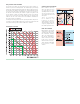
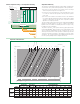


Particle separation rating – dirt separator efciency
1000
Efficiency
50 passages (0.5 m/s)
50
20
10
40
20
0
60
80
100
Efficiency (%)
Efficiency
50 passages (1 m/s)
Particle
dimensions
(µm)
0
5
16
35
63
105
150
250
210
500
WORKING ZONE
CARTRIDGE FILTERS
SPECIAL STRAINERS
Y-STRAINERS
Separated quantity
Initial quantity
.
100%
(
)
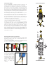
Non-ferrous and ferrous impurities
®
Separation efciency
The capacity for separating the impurities in the medium circulating in the
closed circuits of the systems basically depends on three parameters:
1) It increases as the size and mass of the particle increase. The larger
and heavier particles drop before the lighter ones.
2) It increases as the speed decreases. If the speed decreases, there
is a calm zone inside the dirt separator and the particles separate
more easily.
3) It increases as the number of recirculations increases. The medium in
the circuit, flowing through the dirt separator a number of times during
operation, is subjected to a progressive action of separation, until the
impurities are completely removed.
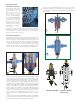
The special design of the internal element in the Caleffi DISCALDIRTMAG
®
magnetic air and dirt separators, are able to completely separate the
impurities in the circuit down to a minimum particle size of 5 μm (0.2 mil),
including 100% ferrous impurities.
The particle separation — dirt separator efficiency graph (left) illustrates
how DISCALDIRTMAG
®
quickly separates nearly all the impurities. After
only 50 circulations, approximately one day of operation, up to 100% is
effectively removed from the circuit for particles of diameter greater than
100 μm (3.9 mil) and on average up to 80% taking account of the small-
est particles. The continual passing of the medium during normal opera-
tion of the system gradually leads to complete dirt removal.
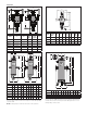
Hydraulic characteristics
0.56
G (l/s) (gpm)
(kPa)
2.8
1.4
0.33
0.39
0.44
0.50
0.69
0.83
0.97
1.1
1.25
1.7
1.9
2.2
2.5
3.3
3.9
4.4
5.0
6.9
11
12
5.6
8.3
9.7
14
2”
2 1/2”
28
17
19
22
25
3”
4”
33
39
44
50
56
5”
6”
0.
1
0.
05
0.09
0.08
0.07
0.06
0.035
0.04
0.045
0.12
0.14
0.16
0.18
0.25
0.3
0.35
0.
2
1
0
.
1
0
.
2
0
.
5
0.9
0.8
0.7
0.6
0.12
0.14
0.16
0.18
0.25
0.3
0.35
0.4
0.45
1.2
1.4
1.6
1.8
2.5
3
2
1
0.
5
0.9
0.8
0.7
0.6
0.45
0.4
0.09
0.08
0.07
0.06
0.025
0.03
0.
0
2
(
ft of water
)
Δ
P
(
ft of water
)
100
10
5
20
50
1000
200
500
0.
1
0.
05
0.09
0.08
0.07
0.06
0.035
0.04
0.045
0.12
0.14
0.16
0.18
0.25
0.3
0.35
0.
2
1
0.
5
0.9
0.8
0.7
0.6
0.45
0.4
0.025
0.03
0.
0
2
6
7
8
9
12
14
16
18
25
3
0
35
40
45
60
70
80
90
120
140
160
180
250
400
45
0
300
350
600
700
800
900
1.2
1.4
1.6
1.8
2
6
4.5
1.2
1.4
1.6
1.8
2
69
83
97
111
125
2000
1200
1400
1600
1800
4
3.5
5
8”
4.3
4.0
3.5
3.0
2.7
2.2
0.27
0.25
0.22
0.19
0.17
0.14
1”
1 1/4”
3/4”
1 1/2” 5461
2” 5461
10”
12”
14”
ft of water x .433 = psi
Brass body Steel union Steel anged body
Size ¾" 1" 1¼" 1½" 2" 2" 2 ½" 3" 4" 5" 6" 8" 10" 12" 14"
4.0 f/s
GPM 6 10 15 22 39 39 60 90 160 245 355 625 980 1,410 1,920
l/s 0.4 0.63 0.95
1.04
2.5 2.5 4.0 6.0 10 15 22 40 62 89 121
10.0 f/s
GPM 55 98 100 155 220 400 615 880 1,570 2,450 3,525 4,800
l/s 3.5 6.2 6.3 9.8 14 25 39 55 99 155 222 303
Cv 19 32 40 50 79 87 174 208 324 520 832 1,109 1,387 1,664 1,967