
Product Overview


Replacement parts
Drain valves (5) & (7), code 538402 FD. Drain valves (8), separator sizes
2" - 6", code NA39753; separator sizes 8", code NA59600.
Insulation shells
The brass DISCALDIRTMAG
®
5461 series can be supplied with the
optional insulated cover, code CBN546002 series (purchased sepa-
rately), to minimize heat loss.
Technical specications
Material: closed cell expanded PE-X
Thickness: 25/64" (10 mm)
Density: - inner part 1.9 lb/ft
3
(30 kg/m
3
)
- outer part: 5.0 lb/ft
3
(80 kg/m
3
)
Thermal conductivity (DIN 52612):
- at 32°F (0°C): 0.263 BTU·in/hr·ft
2
·°F (0.038 W/(m·K)
- at 104°F (40°C): 0.312 BTU·in/hr·ft
2
·°F (0.045 W/(m·K)
Coefficient of resistance to water vapor (DIN 52615): >1,300
Working temperature range: 32–230°F (0–110°C)
Reaction to fire (DIN 4102): CLASS B2
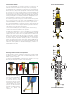
Removing insulation and
draining impurities
1. Remove the insulation by taking off
the bottom casing of the collection
chamber first, and if necessary, the
top insulation casing later.
2. Remove the magnetic ring containing
the magnets, that during operation
attracted the ferrous particles.
3. Flush out the ferrous and nonferrous
debris by turning the handle to open
the drain valve.
4. When finished, replace the
insulationshells.
F39807
59829
59756
F39807
59829
59756
Code Size
CBN546002
¾", 1", 1¼"
Brass 546 only
CBN546118
1½"
Steel 5461 only
CBN546119
2"
Steel 5461 only
A replacement air vent assembly for
the brass and steel DISCALDIRTMAG
®
5461 series is code 59829; for the steel
DISCALDIRTMAG
®
NA546_M series is
code 59756.
The moving parts that control air vent-
ing are accessed
simply by remov-
ing the upper
cover. Replace-
ment cap and float
assembly for all
versions of the brass and steel DISCALDIRTMAG
®
5461 series is code F39807.
When cleaning, simply unscrew the portion of the
body containing the automatic air vent.
1.4
1.8
0.060
0.040
0.20
0.27
0.53
0.47
2.00
2.33
2.67
0.23
0.30
0.40
0.17
0.33
0.67
1.67
3.33
3.00
0.60
1.00
1.33
0.13
0.10
0.053
0.033
0.067
0.047
G (l/
s
)
(gpm)
2.2
4.4
8.8
22.0
2.6
3.0
3.5
3.96
5.3
6.15
7.045
7.9
11.0
13.2
15.4
17.6
19.8
0.5
1
2
5
10
0.1
0.2
9
8
7
6
4
3
1.6
1.2
0.8
0.6
0.7
0.9
0.4
0.3
0.18
0.12
0.16
0.14
∆
P (kPa)
0.25
0.35
0.45
2.5
3.5
4.5
0.83
1.17
1.50
0.083
0.12
0.15
1.1
1.3
1.5
1.7
1.98
0.88
0.20
0.26
0.073
1.5
1.3
1.2
1.0
0.9
0.58
0.41
0.23
0.17
0.12
0.09
0.10
0.13
0.06
0.04
0.026
0.017
0.023
0.020
(PSI)
0.036
0.05
0.07
0.36
0.51
0.65
0.71
0.16
0.029
0.016
∆p (ft. of water)
139
278
556
1388
167
194
222
250
333
389
444
500
694
833
972
1111
1250
69
83
97
111
125
56
DISCALDIRT
®
/
DISCALDIRTMAG
®
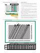
curve
3/4”– Cv =19
Y-strainer curve
3/4” - Cv=8.2
Comparison of head losses:
air and dirt separator to Y-strainers
Y-strainers entrap dirt within a basket made of stainless steel or brass
mesh, selected for the size of the largest particle. Particles smaller
than the mesh size may pass through. On most Y-strainers, the basket
must be removed periodically to clear the trapped debris. As the debris
collects in the basket, flow is impeded resulting in increasing pressure
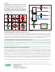
drop and therefore higher head loss. The dirt separation function in the
DISCALDIRTMAG
®
performs exactly as it does in the DIRTCAL
®
, utilizing
the low-velocity-zone principle. The flow velocity of fluid flowing into the
dirt separation chamber is greatly reduced causing the entrained dirt
particles to drop due to their density.
The internal element provides surfaces that assist in separating dirt particles
and guide them downward to ultimately settle to the bottom of the
separator. The dirt separator only creates about 25% of the pressure
drop of a comparable sized, clean basket strainer, depending on mesh
size and amount of filtered debris. These head losses are not affected
by the amount of dirt collected.