
Brochure


13
57
1216
57
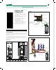
LOW LEAD PRE-ADJUSTABLE PRESSURE REDUCING VALVES
Working pressures
The zone exposed to upstream pressure is constructed so that it
can even operate at high pressure. The PTFE anti-extrusion rings
on
the compensating piston make it possible for the valve to be used
continuously at upstream pressures up to 300 psi.
Non-sticking materials
The central support assembly, containing moving parts, is made
of plastic material with a low adherence coefficient. This solution
minimizes the chance of lime scale formation, a common cause of
malfunctions.
Stainless steel stem
The stainless steel stem makes it possible to minimize the typical
problems associated with the use of hard and aggressive water.
Contoured membrane
The membrane is designed with a special shape to assure more
accurate pressure regulation in accordance with downstream
pressure fluctuations.
This feature also extends the life of the valve, since the diaphragm is
more resistant to sudden pressure fluctuations and to normal wear.
Compact dimensions
The “inclined” configuration makes for more compact dimensions
of 535..H series pressure reducing valves with consequent easy
installation, especially in domestic systems.
Removable self-contained cartridge
The cartridge containing the membrane, strainer, seat, shuttle and
compensating piston is a pre-assembled self-contained unit with a
cover, and can be removed to allow for inspection and maintenance
procedures.
The special construction of the regulating element does not require
any modification of the setting pressure value, which may be left
unchanged.
High temperatures
The materials used for the construction of this series of pressure
reducing valves allow installation also on the hot water circuit with
temperatures of up to 180°F.
Pressure gauge
The optional pressure gauge shows the exact downstream pressure
value regardless of the adjusted knob pressure setting. For special
conditions, e.g. in the presence of a downstream water heater, the
pressure may rise above the set value.
Certification
Series 535..H pressure reducing valves comply with the requirements
of all appropriate or local standards and codes.
bar
0
2
4
10
8
6
psi
0
30
60
150
120
90
|
|
|
|
|
|
|
|
|
|
|
|
|
|
|
|
|
|
|
|
|
|
|
|
|
|
|
|
|
|
|
|
|
|
|
|
|
|
|
|
|
|
|
|
|
|
|
|
|
|
|
|
|
|
|
|
|
|
|
|
|
|
|
|
|
|
|
|
|
|
|
|
|
|
|
|
|
|
|
|
|
|
|
|
|
|
|
|
|
|
|
|
|
|
|
|
|
|
|
|
|
|
|
|
|
|
|
|
|
|
|
|
|
|
|
|
|
|
|
0
60
20
40
80
100
0
1
2
5
6
7
3 4
psi
bar
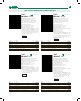
Construction details
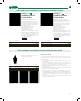
Pre-adjustment
Pressure reducing valves in the 535...H
series are fitted with an operating knob
and a pressure setting indicator which
is visible on both sides. This pressure
indicator features incremental step
operation, therefore the pressure can
be adjusted continuously with the value
displayed at 15 psi increments.
The system pressure can therefore
be pre-set to the desired value, even
before the pressure reducing valve is
installed.
535 H S eri es
35
45
50
2.5
3
3.5
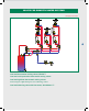
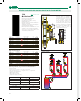
Pressure balanced seat
Caleffi pressure reducing valves are
fitted with pressure balanced seats.
This means the setting pressure
value remains constant, regardless of
variations in the upstream pressure
value. In the figure, the thrust towards
the opening is counterbalanced by the
force created by the closing pressure
acting on the compensating piston.
Since the piston has a surface area
equal to the shuttle one, the two forces
cancel each other out.
The special cross-section of the
passage zone between the seat and
shuttle seal makes for stable behavior
in relation to upstream pressure
fluctuations and operation with high
flow rates, with reduced noise levels
caused by the passage of water.
bar
0
2
4
10
8
6
bar
0
2
4
10
8
6
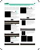
Low head losses
The internal fluid dynamic structure of the pressure reducing valve
allows the achievement of very low head losses, even if a large number
of faucets are opened.