
Product Overview


T
Key to symbols
Safety relief valve
Check valve
Isolation valve
Expansion vessel
Filter
Pump
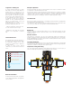
Radiant heating system application
C
A
L
E
F
F
I
CA
L
E
F
F
I
CALEFFI
10
0
8
6
4
2
10
0
8
6
4
2
CALEFFI
10
0
8
6
4
2
10
0
8
6
4
2
10
0
8
6
4
2
10
0
8
6
4
2
CALEFFI
CALEFFI
HOTCOLD
MIX
Radiant loop
MIN
M
A
X
7
1
2
Domestic water system with recirculation
MI
N
M
A
X
7
1
2
STORAGE
HOT WATER
HEATER
COLD
BLUE
HOT
RED
MIX
MIN
M
A
X
7
1
2
RETURN
SUPPLY
Applications diagrams
T
Key to symbols
Safety relief valve
Check valve
Isolation valve
Expansion vessel
Filter
Pump
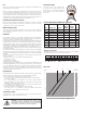
Domestic water system with recirculation
MI
N
M
A
X
7
1
2
1
2
Globe Valve
STORAGE
HOT WATER
HEATER
For domestic recirculating systems that include a single ASSE 1017
point-of-distribution thermostatic mixing valve, such as the Caleffi
5231 series thermostatic mixing valves, the piping installation below
is recommended.
In any reciculating hot water distribution system there will be times
when the circulator is operating, but no hot water is being drawn at
the fixtures. Under this condition, heat continually dissipates from
the piping forming the recirculation loop. If the loop is relatively
short, and well insulated, the rate of heat loss should be very small.
If the loop is long, and uninsulated, the rate of heat loss could be
substantially greater.
To maintain the recirculating water at the desired delivery temperature
the heat lost from the loop must be replaced. This requires some
water flow between the loop and the hot water source. Ideally, this
flow is adjusted so that the rate of heat trasfer from the hot water
source to the loop exactly balances the rate of heat loss from the
loop's piping.
The figure (below right) shows a "bypass valve" (1), and "return
valve" (2), which regulates how much warm water from the return
side of the recirculating loop flows back to the storage tank. When
there is no demand for hot water at the fixtures, the flow of return
water to the tank will equal the rate of hot water flow from the tank to
the inlet port of the mixing valve. Ideally, this flow should be adjusted
so that the rate of heat transfer from the tank to the recirculating
loop exactly balances the rate of heat loss from the recirculating
loop. This allows the water temperature leaving the mixing valve to
remain stable.
The bypass valve (1) and possibly the return valve (2) must be
adjusted when there is no domestic water draw on the recirculating
loop (when all the fixtures are off). Begin with the bypass valve
(1) fully closed, and the return valve (2) fully open. Turn on the
recirculating circulator and let it run for several minutes. The supply
water temperature leaving the mixing valve will likely be lower than
the setting of the valve, since there is no return flow to the tank.
Slowly open the bypass valve (1) and monitor the temperature
leaving the mixing valve. It will likely begin rising as some water
returns to the tank, and an equal flow of hot water moves from
the tank to the hot port of the mixing valve. When the temperature
leaving the mixing valve remains stable, and is at or very close to the
temperature set on the mixing valve, the bypass valve is correctly
set.
The return valve (2) can remain fully open unless a situation occurs
where the bypass valve (1) is fully open, but the temperature leaving
the mixing valve is still too low. If this occurs, partially close the
return valve (2) to add flow resistance. This forces more flow through
the bypass valve (1). Repeat the previously described procedure
of slowly opening the bypass valve (1) until the water temperature
leaving the mixing valve is stable.
Recirculation with point-of-distribution thermostatic mixing valves