
Product Overview
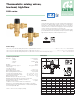


Use
Caleffi 5231 series thermostatic mixing valves are designed to be installed at the hot
water heater (ASSE 1017 models).
ASSE 1017 models are designed to be installed at the hot water heater and cannot
be used for tempering water temperature at fixtures as a point-of-use valve. They
are not designed to provide scald protection or anti-chill service and should not be
used where ASSE 1070 devices are required. Wherever a scald protection feature is
required, ASSE 1070 model mixing valves need to be installed. For safety reasons, it
is advisable to limit the maximum mixed water temperature to 120°F.
Instantaneous production of hot water
Caleffi 5231 series thermostatic mixing valves should not be used in conjunction
with boilers giving instantaneous production of domestic hot water. This would
compromise the correct operation of the boiler.
Radiant heating systems
Caleffi Series 5231 thermostatic mixing valves can also be used for controlling the
flow temperature in radiant heating systems, for constant and accurate control with
ease of installation.
Installation
Before installing a Caleffi 5231 series thermostatic mixing valve, the system must be
inspected to ensure that operating conditions are within the range of the mixing valve,
checking, for example, the supply temperature, supply pressure, etc.
Systems where the Caleffi 5231 series thermostatic mixing valve will be installed must
be drained and cleaned out to remove any dirt or debris which may have accumulated
during installation. Failure to remove dirt or debris may affect performance and the
manufacturer’s product guarantee. Demineralized water use is highly recommended
as the warranty is voided if used on water with hardness greater than 10 grains.
The installation of filters of appropriate capacity at the inlet of the water from the supply
line is always advisable.
The water must be sufficienctly treated before it enters the valve in areas with highly
agressive water. Caleffi 5231 series thermostatic mixing valves must be installed in
accordance with the diagrams in this manual, taking into account all current applicable
standards.
Caleffi 5231 series thermostatic mixing valves can be installed in any position, either
vertical or horizontal.
The following are shown on the thermostatic mixing valves body:
- Hot water inlet, color red.
- Cold water inlet, color blue.
- Mixed water outlet, marked “MIX”.
In systems with thermostatic mixing valves, check valves must be installed to prevent
undesirable fulid backflow. The 5231 is approved to ASSE 1017, and as such does
not contain integral check valves, so those must be sourced separately. It is essential
that access to the valve is totally unobstructed for any maintenance which may be
required to the valve or connections. The piping from/to the valve must not be used
to support the weight of the valve itself.
Commissioning
After installation, the valve must be tested and commissioned in accordance with the
instructions given below, taking into account current applicable standards.
1) The system must be clean and free from any dirt or debris
before commissioning the thermostatic mixing valves. Be sure water hardness
is less than 10 grains.
2) It is recommended that the temperature is set using a suitable calibrated
digital thermometer. The valve must be commissioned by measuring the
temperature of the mixed water at the outlet.
3) The maximum outlet temperature from the valve must be set taking account
of the fluctuations due to simultaneous use.
4) Adjust the temperature using the adjusting knob on the valve.
For safety reasons, it is advisable to limit the maximum mixed water
temperature to 120°F in domestic hot water systems.
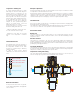
Temperature setting
The temperature is set to the required value by means of the knob with the
graduated scale, located on the top of the valve.
Locking the setting
Position the knob at the required value,
unscrew the top screw, slide off the knob and
put it back in such a way that the handle fits
into the internal slot of the knob. Tighten the
head screw
.
M
I
N
M
A
X
7
1
2
3
Caution: In systems with thermostatic mixing valves,
check valves must be installed to prevent undesirable
fluid backflow. The 5231 models do not contain integral
check valves, and must be sourced separately.
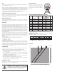
Flow curve
Point of Distribution ASSE 1017 Approved
Min 1234567Max
77 84 91 102 109 118 126 136 149
Pos.
T (ϒF)
with: T
HOT
= 155ϒF (68ϒC) · T
COLD
= 55ϒF (13ϒC) · P = 43 psi (3 bar)
25 29 33 39 43 48 52 58 65T (ϒC)
95
104
35
40 43 47 50 54 58 61 66
109
117
122
129
136 142 150
INLET
Setting the temperature
The temperature is set to the required value by means of the adjusting
knob with the graduated scale on the top of the valve.
Size
Connection
Model
Min.
Flow**
(GPM)
Max.
Flow**
(GPM)
CV
1" NPT 523160A* 4.4 40 7
1" Sweat 523168A* 4.4 40 7
1 ¼" NPT 523170A* 4.4 40 7.6
1 ¼" Sweat w/ temp 523177A* 4.4 40 7.6
1¼" Sweat 523178A* 4.4 40 7.6
1 ½" NPT 523180A 8.8 70 13
1 ½" Sweat 523188A 8.8 70 13
2" NPT 523190A 8.8 70 14.2
2" Sweat 523198A 8.8 70 14.2
*cUPC listing pending.
**Recommended flow rates for temperature stabilty:
± 3°F (± 2°C).
.1
0.1
1
0.2
0.3
0.5
.3
1
p (psi)
G
(l/s) (
gpm
)
10
2
3
5
20
0.1
1
0.2
0.3
0.5
(psi) (bar)
10
2
3
5
20
10
2
5
20
0.01
0.1
0.02
0.03
0.05
1.0
0.2
0.3
0.5
4
0.4 0.4
4
0.04
0.4
50
100
1.5
3.25
1” 1 1/2” 2”
1 1/4”
∆p
∆