
Install Instructions

7
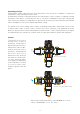
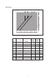
Locking the setting
Position the knob at the required value,
unscrew the top screw, slide off the knob and
put it back in such a way that the handle fits
into the internal slot of the knob. Tighten the
head screw
.
M
I
N
M
A
X
7
1
2
3
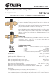
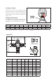
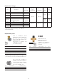
Index
Point
Dimensions
A
Sweat version
E
D
A
30
50
70
90
110
130
150
170
190
210
F
A
F
E
D
B B
C
A
A
HC
Code A B C D E F Wt (lb)
523160A 1" NPT 4" 8" 7 5/8" 4 3/16" 3 3/8" 7.0
523168A 1" SWT 3 5/16" 6 5/8" 7" 3 1/2" 3 3/8" 7.0
523170A 1 1/4" NPT 4 1/8" 8 1/4" 7 3/4" 4 5/16" 3 3/8" 7.0
523177A 1 1/4" SWT 3 3/8" 6 3/4" 7 5/8" 4 1/8" 3 3/8" 9.0
523178A 1 1/4" SWT 3 3/8" 6 3/4" 7" 3 1/2" 3 3/8" 7.0
523180A 1 1/2" NPT 5 1/8" 10 1/4" 9 3/16" 5 7/16" 3 3/4" 17
523188A 1 1/2" SWT 4 1/16" 8 1/8" 8 1/8" 4 3/8" 3 3/4" 17
523190A 2" NPT 5 1/8" 10 1/4" 9 1/2" 5 3/4" 3 3/4" 18
523198A 2" SWT 4 5/16" 8 5/8" 8 5/8" 4 7/8" 3 3/4" 18
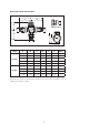
Setting the temperature
The temperature is set to the required value
by means of the adjusting knob with the
graduated scale on the top of the valve.
Pos. Min 1 2 3 4 5 6 7 Max
T (°F) 95 104 109 117 122 129 136 142 150
T (°C) 35 40 43 47 50 54 58 61 66
with: T
HOT
= 155°F (68°C) · T
COLD
= 55°F (13°C) · P
INLETS
= 43 psi (3 bar)