
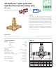
Product Overview

1
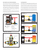
Tmix = Tset + 18°FBY- PASS CLOSING
by-passclosed
system return open
Tf >Tmix≥Ts et +18°F, Tmix=Tr
3
Tf ≤ Tset SYSTEM STARTUP
by-passopen
system return closed
Tf ≤Tset, Tmix=Tf
f
Tmix > Tset + 18°FSYSTEMLOADED
by-passclosed
system return open
Tf >Tmix>Tset +18°F, Tmix=Tr
Tf > Tset STARTOFSYSTEMLOADING
by-passopen
systemreturn open
Tf >Tset, Tr <Tset, Tmix=Tset
2
4
f
f
NON-
CONDENSING
BOILER
NON-
CONDENSING
BOILER
NON-
CONDENSING
BOILER
NON-
CONDENSING
BOILER
NON-
CONDENSING
BOILER
NON-
CONDENSING
BOILER
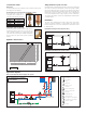
1"
1-1/4"
∆p
(2)
(4)
.16
.33
.83
1.6
3.3
5.5
(88)
(44)
(22)
(9)
ft of hd (psi)
48 (21)
33 (14.5)
16 (7)
10 (4.3)
7 (3)
3.5 (1.5)
1.6 (0.7)
∆p kPa
150
100
50
30
20
10
5
Cv: size 1", 10
size 1-1/4", 14
Flow rate
l/s (gpm)
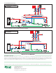
Air separator
Dirt separator
Pump
Shut-off valve
Expansion vessel
Check valve
Motorized mixing valve
Pressure reducing valve
Filling unit
Backflow preventer
Safety relief valve
Dirt separator for vertical pipes
Air separator for vertical pipes
Hydraulic separator
Y-strainer
NON-
CONDENSING
BOILER
Air separator
Dirt separator
Pump
Shut-off valve
Expansion vessel
Check valve
Motorized mixing valve
Pressure reducing valve
Filling unit
Backflow preventer
Safety relief valve
Dirt separator for vertical pipes
Air separator for vertical pipes
Hydraulic separator
Y-strainer
NON-
CONDENSING
BOILER
1
Tmix = Tset + 18°FBY- PASS CLOSING
by-passclosed
system return open
Tf >Tmix≥Ts et +18°F, Tmix=Tr
3
Tf ≤ Tset SYSTEM STARTUP
by-passopen
system return closed
Tf ≤Tset, Tmix=Tf
f
Tmix > Tset + 18°FSYSTEMLOADED
by-passclosed
system return open
Tf >Tmix>Tset +18°F, Tmix=Tr
Tf > Tset STARTOFSYSTEMLOADING
by-passopen
systemreturn open
Tf >Tset, Tr <Tset, Tmix=Tset
2
4
f
f
NON-
CONDENSING
BOILER
NON-
CONDENSING
BOILER
NON-
CONDENSING
BOILER
NON-
CONDENSING
BOILER
NON-
CONDENSING
BOILER
NON-
CONDENSING
BOILER
Sizing method/set point selection
Knowing the BTU output and thermal head on the boiler, the boiler flow
rate can be calculated. Use the hydraulic characteristics graph to identify
the pressure drop of the valve. The valve size can then be selected from
the pressure drop value with the available head of the system pump. The
thermostatic set point (°F) must be selected to control a mixed return
to the boiler temperature that is high enough to prevent condensation,
also using the information or instructions supplied by the manufacturers
of solid fuel boilers.
Installation
The valve can be installed on both sides of the boiler in any position,
vertical or horizontal. Installation is recommended on the return to the
boiler in mixing mode. It can also be installed on the flow from the boiler
in diverting mode.
Installation in mixing mode (boiler protection)
Construction details
Hydraulic characteristics
Installation in diverting mode (system control)
Application diagrams
Non-condensing boiler, direct supply to the system
Brass body
The brass body prevents the formation of ferrous residues in the system,
prolonging boiler operating life.
Thermostatic sensor replacement to modify the setting
The thermostatic sensor can be
easily replaced for maintenance or
set pointchange without removing.
Code Description
F29633 115 ° F
F29634 130°F
F29635 140°F
F29636 160°F
Temperature gauge pocketwells
The boiler protection mixing valve body features
temperature gauge pocket wells on front and rear
sides, allowing installation of a temperature gauge
(codeF29571) for monitoring the working temperatures:
by-pass from boiler, return from system, and mixed
toboiler.
Use safety devices according to
local regulations
*Air purge recommended for boiler loop
*