
Install Instructions

3
1
a
b
c
d
Installation
Assembly and disassembly should always be conducted when the system is cold and not under
pressure.
Accessibility: it is essential to provide unobstructed access to the valve for maintenance of the
valve or fittings.
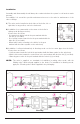
1) The valve can be installed on both sides of the boiler, left- or
right side, in any position, vertical or horizontal.
2) Installation is recommended on the return to the boiler in
mixing mode (boiler protection).
Connections as follows:
- Hot water from boiler: inlet in the port marked with the
red dot (2) (see label).
- Cool system water return: inlet in the port marked with the
blue dot (1) (see label).
- Mixed water outlet, returning to the boiler, in the port
marked with the flame symbol on the valve body
3) Installation is allowed alternatively in diverting mode on the hot water pipe from the boiler.
Connections as follows:
-
Hot flow water from boiler: inlet in the port marked with the flame symbol on the valve body.
-
Outlet of the water towards the system flow: in the port marked with the blue dot (1) (see label).
- Water by-pass outlet: in the port marked with the red dot (2) (see label).
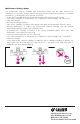
NOTE: The valve is supplied as standard for installation in mixing valve mode, with the
“Mixing valve” labels already applied to the body. For installation in diverting mode,
apply the “Diverting valve” labels supplied in the packaging.
Diverting
3
2
1
2
1
Boiler protection (mixing)
2
2
1
2
1