
Submittal Sheet


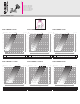

a) As the thermal fluid passes,
measure the Δp of the valve
wany suitable differential pressure
measuring device(fig. G);
b) Using the “Hydraulic characteristics”
sheet (sheet code 18169 supplied
in the pack), find the flow rate value
that is passing through the valve,
consulting the Venturi diagram
“Δp-flow rates” corresponding to
the size of the valve used.
c) Turn the knob and repeat steps a)
and b) until you reach the desired
value.
Correction for liquids of different
densities
If using liquids with a density
different from water at 70°F
(20°C) ≈ 62.4 lb/ft
3
( ≈ 1 kg/
dm3), correct the value of the
measured head loss Δp using the
following formula:
Memory Stop on the
balancing valve
G
Δp
1
=
Δp
where:
Δp
1
= reference head loss in (psid(kPa))
Δp = measured head loss in (psid(kPa))
= fluid density in lb/ft
3
(kg/dm
3
)
After balancing the flow rate, insert
a 2.5 mm hexagonal spanner in
the hole (7), turn counter-clockwise
until the red indicator (8), initially not
visible, is aligned with the top edge
of the knob, without forcing it. This
operation allows you to close the
valve and open it again until the set
value is reached (fig. H ).
NOTE: the sticker (9) on the top of the
knob indicates: “Yes”=Memory stop
on; “No”=Memory stop off.
H
7
9
8
water
·