
Submittal Sheet


Operating Principle
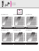
The opening position is indicated by two
numbered indicators (fig. E):
- The turn indicator (1) shows a flow
rate scale from 0 to 6 (0 closure, 5
maximum flow rate, 6 completely wide
open flow) in red.
Turning the knob manually through
360° causes the indicator to click by
one unit.
- The micrometric control indicator
(2) shows numbers in black from 0
to 9. Each change in this number
represents 1/10 of an opening/closing
turn of the valve with respect to the
turn indicator (1).
E
Use of the balancing
valve: setting the
flow rate (fig F-G)
NOTE: the indications + and – on
the drawings refer respectively to the
pressure test ports upstream and
downstream of the Venturi port inside
the valve.
For the connection of the pressure test ports
of the valve (3) with a differential pressure
measuring device (4), use a pair of fittings
with fast-plug syringe (5) ( Caleffi 100 series)
(fig. F).
F
3
5
4
2
1