
Product Overview


Construction details
Polymer ow cartridge
The flow rate cartridge is made of an anti-scale polymer, specially
engineered for use in cooling, heating and domestic water
systems, to prevent mineral buildup
in a wide range of working
temperatures. It features high resistance to the abrasion caused
by continuous fluid flow, is insensitive to the deposit of scale and
is fully compatible with glycols and additives used in circuits.
Exclusive design
With its exclusive design, the flow cartridge is able to accurately
control the flow rate in a wide range of operating pressures. A
special internal chamber acts as a damper for the vibrations
triggered by the fluid flow, allowing low noise operating
conditions to the device.
For these reasons it can be used in systems on zone branch
circuits or directly at the terminals.
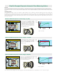
Size the hydronic system with FlowCal automatic balancing
valves as follows:
1. DPMAXCIRCUIT
Determine the pressure head loss for the zone circuit with
the greatest pressure drop (flow resistance). This is true for
any hydronic system with supply and return headers.
As an example, this would be circuit #8 for the 2-pipe direct
return system with circuits having identical resistance,
illustrated to the right, as it is farthest from the pump. If,
however, all circuits are not identical, choose the circuit with
the greatest pressure drop.
2. DPMINFlowCal
Add the minimum differential operating pressure
(2, 4, or 5 psid) required for the FlowCal™ model selected
for the circuit with the greatest pressure drop.
3. PUMP HEAD = DPMAXCIRCUIT + DPMINFlowCal
Pump Sizing using FlowCal
Flow rate table
7654321 8
Control valve
FlowCal
Code
12734xAF • • •
12735xAF • • •
12736xAF • • •
0.35; 0.50; 0.75; 1.00; 1.30; 1.50; 1.75; 2.00; 2.20; 2.50; 2.60; 3.00; 3.50; 4.00; 4.50; 5.00; 6.00; 7.00; 8.00; 9.00; 10.00
0.35; 0.50; 0.75; 1.00; 1.30; 1.50; 1.75; 2.00; 2.20; 2.50; 2.60; 3.00; 3.50; 4.00; 4.50; 5.00; 6.00; 7.00; 8.00; 9.00; 10.00
0.35; 0.50; 0.75; 1.00; 1.30; 1.50; 1.75; 2.00; 2.20; 2.50; 2.60; 3.00; 3.50; 4.00; 4.50; 5.00; 6.00; 7.00; 8.00; 9.00; 10.00
Size
Dp range (psid)
Flow rates (gpm)
2–14
2–32
4–34
5–35
1/2”
3/4”
1”
CARTRIDGE LOCKING NUT
CARTRIDGE
BODY
This is equal to the minimum working Dp of the
FlowCal
cartridge: 2, 4 or 5 psi (13, 27 or 31 kPa).
Minimum differential pressure required