
User Guide

Flow characteristics
The ThermoSetter thermostatic balancing valve is designed to balance individual branches of domestic hot water recirculation systems, based on the
temperature at the valve. It automatically modulates flow to maintain hot water availability to all fixtures in the branch circuit. The valve is at minimum flow (Cv
= .35) when the incoming water temperature is equal to the set-point position of the adjustment dial. The valve opens as incoming water temperature drops.
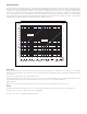
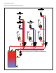
For pressure loss calculations in the recirculation system, follow traditional pipe sizing and head loss practices. For pressure loss calculations across the ThermoSetter
valve, use the design curve shown in the graph below. This line represents a typical valve position under normal working conditions (∆T= 10°F). Determine the
pressure drop across the valve by selecting the branch design GPM on the graph X-axis, draw a vertical line up to the “design” curve, then go across to the Y-axis
to find the design pressure drop. Include that pressure drop in your head loss calculations for the circuit.
2. 5
3 4.5 6 7 8.810 1213.2
0.01
0.02
0.03
0.05
0.07
0.10
0.15
0.20
0.30
0.50
0.70
1.00
1.50
2.00
3.00
4
5
6
7.25
10
14.5
0.70
2.00
Flow rate
(/m) (gpm)
0.40
0.30
0.12
0.10
0.08
1.40
1.80
0.90
0.60
0.30
1.20
0.16
0.20
0.50
0.60
0.90
1.00
1.80
0.36
0.48
2.40
3.00
3.60
4.20
4.80
5.40
6.00
7.80
∆p (psi)
∆p (kPa)
0.1
0.2
0.3
0.5
0.7
1.0
1.4
2.0
3.5
7.0
11
13
20
10˚F ∆T
inlet to setpoint
Operation in
by-pass mode
0.35 Cv
minimum
2.1 Cv
full open
0.69 Cv
design
System sizing
For flow rate calculations in the recirculation system, the pump is sized to provide sufficient flow to compensate for the total heat loss in all the supply
branches to the furthest fixture in each circuit. Heat loss in return lines, downstream of the balancing valves, is irrelevant and not included in the flow
rate calculations.
The flow rate calculation formula to use is: GPM = BTUh/∆T x 500.
Common design practice for recirculation lines is to use a ∆T of 10°F. This is the temperature difference of the recirculating water between the heat
source and to the furthest fixture in each circuit. Assuming the common value of a ∆T = 10°F, the equation simplifies to:
GPM = BTUh/5000.
BTUh heat loss, will vary based on pipe type and insulation. Heat loss tables and charts are available from a variety of sources.
Example:
Calculate the recirculation circuit flow rate for 100 feet of ¾” non-insulated copper pipe. Assume an average heat loss of 30 BTU/h per foot.
30 BTUh per foot x 100 feet = 3000 BTU/h heat loss in the supply piping.
Flow rate = 3000 / 5000 = 0.6 GPM flow required in that circuit.