
Product Overview
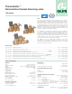

Flow characteristics
The ThermoSetter™ thermostatic balancing valve is designed
to balance individual branches of domestic hot water recirculation
systems, based on the temperature at the valve. It automatically
modulates flow to maintain hot water availability to all fixtures in the
branch circuit. The valve is at minimum flow (Cv = .23) when the
incoming water temperature is equal to the set-point position of the
adjustment dial. The valve opens as incoming water temperature drops.
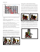
For pressure loss calculations in the recirculation system, follow
traditional pipe sizing and head loss practices. For pressure loss
calculations across the ThermoSetter™ valve, use the design curve
shown in the graph below. This line represents a typical valve position
under normal working conditions (∆T= 10°F). Determine the pressure
drop across the valve by selecting the branch design GPM on the
graph X-axis, draw a vertical line up to the “design” curve, then
go across to the Y-axis to find the design pressure drop. Include
that pressure drop in your head loss calculations for the circuit.
2. 5 3
4.5 6 7 8.810 1213.2
0.01
0.02
0.03
0.05
0.07
0.10
0.15
0.20
0.30
0.50
0.70
1.00
1.50
2.00
3.00
4
5
6
7.25
10
14.5
0.70
2.00
Flow rate
(/m) (gpm)
0.40
0.30
0.12
0.10
0.08
1.40
1.80
0.90
0.60
0.30
1.20
0.16
0.20
0.50
0.60
0.90
1.00
1.80
0.36
0.48
2.40
3.00
3.60
4.20
4.80
5.40
6.00
7.80
∆p (psi)
∆p (kPa)
0.1
0.2
0.3
0.5
0.7
1.0
1.4
2.0
3.5
7.0
11
13
20
10˚F ∆T
inlet to setpoint
Operation in
by-pass mode
0.23 Cv
minimum
1.2 Cv
by-pass
2.1 Cv
full open
0.52 Cv
design
System sizing
For flow rate calculations in the recirculation system, the pump is sized
to provide sufficient flow to compensate for the total heat loss in all the
supply branches to the furthest fixture in each circuit. Heat loss in return
lines, downstream of the balancing valves, is irrelevant and not included
in the flow rate calculations.
The flow rate calculation formula to use is: GPM = BTUh/∆T x 500.
Common design practice for recirculation lines is to use a ∆T of 10°F.
This is the temperature difference of the recirculating water between
the heat source and to the furthest fixture in each circuit. Assuming the
common value of a ∆T = 10°F, the equation simplifies to:
GPM = BTUh/5000.
BTUh heat loss, will vary based on pipe type and insulation. Heat loss
tables and charts are available from a variety of sources.
Example:
Calculate the recirculation circuit flow rate for 100 feet of ¾” non-insulated
copper pipe. Assume an average heat loss of 30 BTU/h per foot.
30 BTUh per foot x 100 feet = 3000 BTU/h heat loss in the supply piping.
Flow rate = 3000 / 5000 = 0.6 GPM flow required in that circuit.
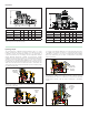
Installation
Before installing the ThermoSetter™, flush the pipes to make sure
that impurities in the system will not interfere with valve performance.
Strainers of sufficient capacity at the inlet from the water main are highly
recommended. The ThermoSetter™ can be installed in any position,
vertical or horizontal, following the flow direction indicated by the arrow
on the valve body. The ThermoSetter™ must be installed according to
the diagrams given in this manual. It must be installed to allow free access
for checking on operation and maintenance procedures.
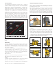
Temperature adjustment and locking
Set the desired recirculation system temperature by turning the
adjustment knob. The graduated scale shows the temperatures at which
the adjustment knob can be set.
After adjusting the temperature, the setting can be locked at the desired
value using the adjustment knob. Unscrew the locking screw at the top
of the adjustment knob, remove the knob and then put it back on so that
the internal groove couples with the protrusion on the knob holder nut.
When this lock is used, the reference of the indication of the temperature
values on the knob is lost. To restore it, completely unscrew the locking
screw. Reposition the knob on MAX value. Insert and tighten the locking
screw.
The “by-pass mode” curve in the chart above shows the head loss of
the valve when it is in by-pass thermal disinfection mode for Legionella
control.