
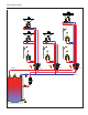
Product Overview

The graph shows the variation of the Cv value depending on the valve
operating mode (A, B, C) and on the inlet temperature of the domestic
hot water.
Operating mode A - Temperature control
Cv max: = 2.1 maximum flow state when operating in temperature
control mode (cartridge fully open).
Cv min: = 0.23 minimum flow state when operating at set point in
temperature control mode (cartridge nearly closed).
Operating mode B - Automatic thermostatic disinfection
Cv dis: = 1.2 maximum flow state when operating in thermostatic
controlled thermal disinfection mode with a temperature of 160°F (70°C).
Operating mode C - Actuator-controlled disinfection
Cv dis: = 1.2 maximum flow state when operating in actuator-controlled
thermal disinfection mode using a thermo-electric actuator, code 656
series.
Cv
max
T (°F)
G (gpm)
Cv
dis
Cv
min
Automatic disinfection
C
Thermal disinfectionTemperature control
100
140
150
160
190
170
180
185
T
set
(2.1)
(1.2)
(0.23)
Cv
design
(0.52)
Operating mode B - Automatic thermostatic disinfection
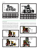
The 1162xx series operating characteristic curves for operating mode B
are curves 1, 2, 3 and 4. When a temperature higher than about 155°F
(68°C) is reached, a by-pass passage begins to open to activate the
second thermostatic cartridge which controls the thermal disinfection
process, allowing flow independent of the operation of the thermostatic
balancing cartridge. This allows water flow through a special by-pass
port, opening the flow path up until the temperature of 160°F (70°C) is
attained shown in curve 3. If the temperature continues rising beyond
this point, the flow is reduced through the by-pass port to allow thermal
balancing even during the disinfection process. When temperature
reaches about 170°F (75°C), the closes the disinfection by-pass port to
protect the system fixtures from the effects of excessive temperatures,
as shown in curve 4.
Operating mode C - Actuator-controlled disinfection
The 1163xx series operating characteristic curves for operating mode
C are curves 1, 2 and 5. When the disinfection operating temperature
setting of the electronic disinfection system is reached, the thermo-
electric actuator 656 series (which is controlled by a dedicated electronic
control system), is energized to operate the by-pass valve to control
the disinfection process, allowing flow independent of the operation of
the thermostatic balancing cartridge shown in curve 5. In this case, the
minimum head loss is produced during this thermal disinfection process.
Thermostatic disinfection by-pass
Thermal shut-off
Electric controlled disinfection by-pass
Operating mode
Operating mode A - Temperature control
At the set temperature, the valve plug, controlled by the thermostatic
balancing cartridge, gradually closes the outlet to the minimum. The outlet
never fully closes to always allow a minimum flow for temperature sensing
and to prevent recirculation pump dead-heading. If the temperature
decreases, the outlet increases, causing flow and thus temperature to
increase back to the set temperature as shown in curve 1. If temperature
exceeds the set-point, the plug stays in the minimum closed position as
shown in curve 2.
Thermostatic balancing control
Minimum flow rate