
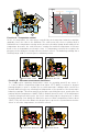
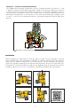
Install Instructions


8
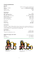
The ThermoSetter™ thermostatic balancing valve is designed
to balance individual branches of domestic hot water recirculation
systems, based on the temperature at the valve. It automatically
modulates flow to maintain hot water availability to all fixtures in the
branch circuit. The valve is at minimum flow (Cv = .23) when the
incoming water temperature is equal to the set-point position of the
adjustment dial. The valve opens as incoming water temperature drops.
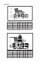
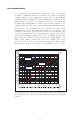
For pressure loss calculations in the recirculation system, follow
traditional pipe sizing and head loss practices. For pressure loss
calculations across the ThermoSetter™ valve, use the design curve
shown in the graph below. This line represents a typical valve position
under normal working conditions (∆T= 10°F). Determine the pressure
drop across the valve by selecting the branch design GPM on the
graph X-axis, draw a vertical line up to the “design” curve, then
go across to the Y-axis to find the design pressure drop. Include
that pressure drop in your head loss calculations for the circuit.
2. 5 3
4.5 6 7 8.810 1213.2
0.01
0.02
0.03
0.05
0.07
0.10
0.15
0.20
0.30
0.50
0.70
1.00
1.50
2.00
3.00
4
5
6
7.25
10
14.5
0.70
2.00
Flow rate
(/m) (gpm)
0.40
0.30
0.12
0.10
0.08
1.40
1.80
0.90
0.60
0.30
1.20
0.16
0.20
0.50
0.60
0.90
1.00
1.80
0.36
0.48
2.40
3.00
3.60
4.20
4.80
5.40
6.00
7.80
∆p (psi)
∆p (kPa)
0.1
0.2
0.3
0.5
0.7
1.0
1.4
2.0
3.5
7.0
11
13
20
10˚F ∆T
inlet to setpoint
Operation in
by-pass mode
0.23 Cv
minimum
1.2 Cv
by-pass
2.1 Cv
full open
0.52 Cv
design
The “by-pass mode” curve in the chart above shows the head loss of
the valve when it is in by-pass thermal disinfection mode for Legionella
control.
Flow characteristics