MACHINIST CALC™ PRO The Machinist Calc™ Pro Advanced Machining Math and Reference Tool (Model 4087) provides fast, precise solutions for your every day machining calculations. With the Machinist Calc Pro you will spend less time looking up your most-needed calculations on charts, in books or on the Internet and more time machining.
Table of Contents GETTING STARTED.............................................................................................5 KEY DEFINITIONS.............................................................................................5 Basic Function Keys.........................................................................................5 Dimensional Function Keys.............................................................................6 Weight and Volume Function Keys....................
RPM – Milling.................................................................................................26 RPM – Turning...............................................................................................27 RPM – Drilling................................................................................................27 FEED RATE......................................................................................................
Changing a Metric Thread Classification......................................................43 Numeric Thread Size.....................................................................................44 Fractional Thread Size...................................................................................46 Metric Thread Size.........................................................................................47 Custom Thread Percentage....................................................
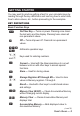
Getting Started You may want to practice getting a feel for your calculator keys by reading through the key definitions and learning how to enter data, how to store values, etc., before proceeding to the examples. KEY DEFINITIONS Basic Function Keys O On/Clear Key — Turns on power. Pressing once clears the last entry and the display. Pressing twice clears all non-permanent values. o Off — Turns all power off. Clears all non-permanent values. +-*� Arithmetic operation keys.
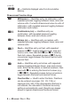
(cont’d) gM M- — Subtracts displayed value from Accumulative Memory. Dimensional Function Keys m Millimeters — Identifies entry as millimeters, with repeated presses toggling between linear, area and volume units. Converts dimensional value to units of millimeters, with repeated presses toggling between millimeters and meters. g5 Centimeters (cm) — Identifies entry as centimeters, with repeated presses toggling between linear, area and volume units.
B 1/1000" (mils) — Multiplies a dimensionless entry by 0.001 Inch and displays the result as Inches. Converts a linear entry to decimal Inches. For both methods, the result is rounded and displayed to three decimal places Weight and Volume Function Keys g6 Tons — Enters or converts a weight or volume value to tons. g4 Pounds (lbs) — Enters or converts a weight or volume value to pounds. g3 Metric Tons (met tons) — Enters or converts a weight or volume value to metric tons.
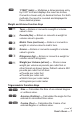
(cont’d) gp Arccosine (ArcCos) — Calculates the angle for the entered or calculated Cosine value. gc Tangent (Tan) — Calculates the Tangent of an entered degree or unitless value. gh Arctangent (ArcTan) — Calculates the angle for the entered or calculated Tangent value. Miscellaneous Functions g. Degrees:Minutes:Seconds (dms◄►deg) — Converts between D:M:S and decimal degree formats; repeated presses will toggle between the two formats. % Percentage — Used to find a given percent of a number.
g= Paperless Tape (Tape) — Accesses the Paperless Tape mode (see Paperless Tape section), which keeps track of your past 30 entries. Useful for checking strings of numbers. gS Preference Settings (Prefs) — Accesses various customizable settings, such as dimensional answer formats (see Preference Settings section). Machinist Function Keys C Cutting Speed — Enters or calculates Cutting Speed. Unitless entries assumed feet per minute in U.S. mode; meters per minute in Metric mode.
(cont’d) f Feed Rate — Enters or calculates Feed Rate. Unitless entries assumed inches per minute in U.S. mode; millimeters per minute in Metric mode. Calculates Feed Rate given values for Cutting Feed and RPM (Spindle Speed) or Feed per Tooth (Chip Load), RPM and Number of Teeth. gf Wire Size — Enters or calculates Wire Size for 3-Wire Measurements. Unitless entries assumed Inches in U.S. mode; millimeters in Metric mode.
gt % Thread — Enters a non-standard Thread Grip Percentage for use in determining screw Tap Drill Sizes. Default value is 75%. D Drill Size — Enters a numeric, letter, fractional or metric Drill Size, displaying the decimal Inch (U.S. mode) or millimeter (Metric mode) equivalent of the Drill Size. The next smaller Drill Size is displayed if the entered value doesn’t match a Drill Size. Repeated presses of D or + toggle through Drill Sizes in increasing order.
(cont’d) d Diameter — Enters a Diameter. Unitless entries assumed Inches in U.S. mode; millimeters in Metric mode. Calculates circle Area and Circumference given entered Diameter. Calculates Diameter given entered Radius. gd Radius — Enters or calculates a Radius. Unitless entries assumed Inches in U.S. mode; millimeters in Metric mode. Calculates Radius given entered Diameter. g8 Alpha — Enters alphabet character selection mode.
n Angle (θ) — Enters or calculates an Angle, providing the Adjacent Angle for both instances. Calculates an Angle given two other righttriangle values. Also enters the Starting Angle of the first hole of a Bolt Pattern, with 0° being the three o’clock position and the rotation going counterclockwise. setting fractional resolutions The Machinist Calc Pro is set to display fractional answers in 64ths of an Inch. All examples in this User’s Guide are based on 1/64".
(cont’d) 3. To permanently set the Fractional Resolution you have selected above, press O (or any key) to set the displayed Fractional Resolution and exit Preference Settings. KEYSTROKE DISPLAY 0. O 4. To recall your selected Fractional Resolution: r/ STD 0-1/64 INCH * 1/64" is the default setting. The display may differ from the example depending on what the resolution is currently set to.
PREFERENCE SETTINGS Press g, then S to access the Preferences menu. Continue pressing S to toggle through different Preferences. Press + or - keys to toggle between options of the different Preferences. Press O to exit Preferences. Your calculator will keep your Preference Settings until a Full Reset alters your settings to the default values (see Appendix for more information).
(cont’d) KEYSTROKE DISPLAY FRAC COnST + + (repeats options) FRAC Std. Seventh press of S : (Mathematical Operation) MATH OrDEr MATH CHAIn + + (repeats options) MATH OrDEr Entering dimensions Note: Unlike other Calculated Industries/Construction Master calculators, the Machinist Calc Pro does not have a dedicated Feet key. Feet is a secondary function located above the 7 key, so you have to use the g key, then 7 to enter or calculate dimensions using Feet. Below are some examples.
Square and Cubic Dimensions Examples of how square and cubic dimensions are entered (press O after each entry): DIMENSIONS 14 square Inches 11 square millimeters 1.5 cubic meters 3 cubic Feet KEYSTROKE 14ii 11mm 1.5g999 3g7g7g7 conversions Linear Conversions Convert 10 Feet 6 Inches to other dimensions, including metric: KEYSTROKE OO 10g76i gB * g7 (Feet) gi gm g5 (cm) g9 (m) DISPLAY 0. 10 FEET 6 INCH 126.000 INCH 10.5 FEET 126. INCH 3200.4 MM 320.04 CM 3.
(cont’d) KEYSTROKE DISPLAY 15 FEET 9-1/2 INCH 15g79i1/2 g7 (Feet) g7 15.791667 FEET 15 FEET 9-1/2 INCH Convert 17.32 Feet to Feet-Inch-Fractions: KEYSTROKE OO 17.32g7 (Feet) =g7 g7 gi g7g7 DISPLAY 0. 17.32 FEET 17 FEET 3-27/32 INCH 17.32 FEET 207.84 INCH 17 FEET 3-27/32 INCH Convert 8-1/8 Inches to decimal Inches. Then convert to decimal Feet. KEYSTROKE OO 8i1/8 gi g7 (Feet) DISPLAY 0. 8-1/8 INCH 8.125 INCH 0.6770833 FEET Convert 9.0625 Inches to fractional Inches. Then convert to decimal Feet.
Square and Cubic Conversions Convert 6 square Feet to other square dimensions: KEYSTROKE OO 6g7g7 (Feet) gm g9 (m) g5 (cm) DISPLAY 0. 6 SQ FEET 557418.24 SQ MM 0.5574182 SQ M 5574.1824 SQ CM Convert 0.05 cubic meters to other dimensions: KEYSTROKE OO .05g999 (m) gm g5 (cm) gi g7 (Feet) DISPLAY 0. 0.05 CU M 50000000. CU MM 50000. CU CM 3051.1872 CU INCH 1.7657333 CU FEET Weight Conversions Convert 1.5 tons to pounds and kilograms: KEYSTROKE OO 1.5g6 (tons) g1 (kg) g4 (lbs) DISPLAY 0. 1.5 TON 1360.
Weight per Volume and Volume Conversions Convert 2 cubic Feet of stainless steel to pounds, tons, kilograms, and metric tons if the steel weighs 7,480 kilograms per cubic meter. KEYSTROKE DISPLAY 0. OO 1. Store the weight per volume: 7480S0000 * (wt/vol) $ 7480. KG/ CU M 2. Enter steel volume: 2g7g7g7 2 CU FEET 3. Convert to pounds, tons, kilograms and metric tons: g4 (lbs) g6 (tons) g1 (kg) g3 (met tons) 933.92229 LBS 0.4669611 TON 423.62003 KG 0.42362 MTON 4.
KEYSTROKE 6g72i1/2+ 11g75i1/4+ 18.25i= -2i1/8= DISPLAY 6 FEET 2-1/2 INCH 17 FEET 7-3/4 INCH 19 FEET 2 INCH 18 FEET 11-7/8 INCH Multiplying Dimensions Multiply 5 Feet 3 Inches by 11 Feet 6-1/2 Inches: KEYSTROKE 5g73i* 11g76i1/2= DISPLAY 5 FEET 3 INCH 60.59375 SQ FEET Multiply 2 Feet 7 Inches by 10: KEYSTROKE 2g77i*10= DISPLAY 25 FEET 10 INCH Dividing Dimensions Divide 30 Feet 4 Inches by 7 Inches: KEYSTROKE 30g74i,7i= DISPLAY 52.
(cont’d) Find 18% of 50 Feet: KEYSTROKE OO 50g7*18% DISPLAY 0. 9. FEET Take 20% from 17 Feet 6 Inches: KEYSTROKE 17g76i-20% DISPLAY 14 FEET 0 INCH MEMORY OPERATION Whenever the M key is pressed, the displayed value will be added to the Memory.
KEYSTROKE 74 5gM (M-) rM M M rr DISPLAY M- 745. & TOTAL - 135. & AVG - 45. & COUNT 3. & M+ - 135. Using Memory Storage Keys (M1- M9) In addition to the standard cumulative Memory (as previously described), your calculator has nine independent Storage Registers – M1 through M9 – that can be used to permanently store single, noncumulative values. The following example shows the use of M1 (S 1). To use M2 - M9, replace the presses of the 1 key with presses of the corresponding number key (2 - 9).
PAPERLESS TAPE OPERATION The Paperless Tape allows you to display and review the last thirty entries of a regular math or basic dimensional math sequence. To access this mode after entering values, press g=. Then, press + or - to scroll forward or backward through the entries. While in the Paperless Tape mode, the display will show the previously entered or calculated value, along with the sequential number of the entry (e.g., 01, 02, 03, etc.
KEYSTROKE DISPLAY 11.5 INCH 7i1/2+ 6i+ 3i3/4= 17.5 INCH 21.25 INCH 2. Access the Tape function: g= TTL = 21.25 INCH 3. Scroll from first value to total: + + + + + 01 4. INCH 02+ 7-1/2 INCH 03+ 6. INCH 04+ 3-3/4 INCH TTL = 21.25 INCH 4. Scroll last two values: 04+ 3-3/4 INCH - 03+ 6. INCH 5. Exit Tape function and add another value to your total: = + 3i1/2= TTL = 21.25 INCH 21.25 INCH 24.75 INCH USING THE MACHINIST CALC PRO IMPORTANT: All examples are based on the default U.S.
RPM (SPINDLE SPEED) RPM is the rotational speed of the spindle in revolutions per minute. In a milling machine or drill, the Spindle Speed is the rotation of the attached cutting tool. In a turning machine, it is the rotation of the attached workpiece. RPM can be calculated given values for Diameter and Cutting Speed. RPM – Milling Calculate the Spindle Speed (RPM) when milling with a .375" bit at a Cutting Speed of 300 sfm (surface feet per minute): Diameter: .375″ RPM KEYSTROKE OO DISPLAY 0. 1.
RPM – Turning Calculate the Spindle Speed (RPM) needed to turn a piece with a 5" Diameter at a recommended Cutting Speed of 650 sfm: KEYSTROKE OO DISPLAY 0. 1. Enter the bit Diameter: 5d DIA $ 5. INCH 2. Enter the Cutting Speed: 650C CUT $ 650. FEET/MIN 3. Calculate the Spindle Speed (RPM): R* RPM 497. * Repeated presses of R will toggle through the inputs and outputs, starting with the entered Cutting Speed.
FEED RATE Feed Rate is the speed of the cutting tool’s movement relative to the workpiece as the tool makes a cut. You can calculate Feed Rate given values for Cutting Feed and RPM (Spindle Speed). If you don’t know the Cutting Feed, you can calculate Feed Rate with Feed per Tooth (Chip Load), Number of Teeth and RPM. Feed Rate – Based on Cutting Feed and RPM (for Turning) Calculate the Feed Rate if you are turning a 1" steel round stock down with a Cutting Feed of 0.
KEYSTROKE DISPLAY 2. Enter the RPM: 800R RPM $ 800. 3. Calculate the Feed Rate: FEED 3.2000 INCH/MIN f* * Repeated presses of f will toggle through the inputs and outputs, starting with the entered RPM (Spindle Speed). Feed Rate – Based on Feed per Tooth, RPM and # of Teeth Calculate the Feed Rate for a four-fluted end mill using a Feed per Tooth (Chip Load) of 0.005 Inch turning at 1,000 RPM (Spindle Speed): RPM: 1000 Number of Teeth: 4 Feed per Tooth: 0.
(cont’d) KEYSTROKE DISPLAY 3. Enter the RPM: 1000R RPM $ 1000. 4. Calculate the Feed Rate: f f f FEED 20.0000 INCH/MIN RPM $ 1000. CUT $ 0.02 INCH/REV* * This Cutting Feed is calculated based on the entered Feed/Tooth and Number of Teeth. It, along with RPM, is then used to calculate the Feed Rate. Cutting Speed Cutting Speed is the speed of the workpiece surface relative to the edge of the cutting tool during a cut, typically measured in surface feet per minute.
KEYSTROKE C rC * DISPLAY RPM $ 1250. CUT $ 163.62462 FEET/MIN * The calculated Cutting Speed is displayed as a rounded, whole number value. r C displays the stored Cutting Speed value in decimal floating point format. Cutting Speed – Turning Calculate the Cutting Speed when turning a 4" rod at 300 RPM (Spindle Speed): KEYSTROKE DISPLAY 0. OO 1. Enter the Diameter of the rod: DIA $ 4. INCH 4d 2. Enter the RPM: RPM $ 300. 300R 3. Calculate the Cutting Speed: C* CUT 314.
(cont’d) KEYSTROKE DISPLAY 2. Enter the RPM: 750R RPM $ 750. 3. Calculate the Cutting Speed: C* CUT 81. FEET/MIN * Repeated presses of C will toggle through the inputs and outputs, starting with the entered Diameter. Cutting Speed – Using Metric Mode If you know you’re going to be making your calculations in metric units, you can easily set your calculator to Metric Mode prior to entering values.
* Repeated presses of C will toggle through the inputs and outputs, starting with the entered Diameter. FEED PER TOOTH (CHIP LOAD) Feed per Tooth, or Chip Load, is the thickness of material removed by each cutting surface. You can calculate Feed per Tooth given values for Number of Teeth and Cutting Feed. If the Cutting Feed is not known, the Feed per Tooth can be calculated given values for Number of Teeth, Feed Rate and RPM (Spindle Speed).
Feed per Tooth – Based on Feed Rate, RPM and # of Teeth Calculate Feed per Tooth (Chip Load) with a 12.8 Inch per minute Feed Rate, 4 Teeth and a Spindle Speed of 800 RPM: KEYSTROKE DISPLAY 0. OO 1. Enter the Feed Rate: 12.8f FEED $ 12.8 INCH/MIN 2. Enter the Number of Teeth: 4# TEETH $ 4. 3. Enter the Spindle Speed (RPM): 800R RPM $ 800. 4. Calculate the Feed per Tooth: F* FPT 0.
KEYSTROKE 6BF DISPLAY FPT $ 0.006 INCH 2. Enter the Tool Diameter: DIA $ 1. INCH 1d 3. Enter Cut Depth: .1gC (Cut Depth) DEPTH $ 0.1 INCH 4. Calculate the adjusted Feed per Tooth: C ADJST 0.0100 INCH 5. Calculate the Radial Chip Thinning Factor: C C C RCTF 1.6667 INCH DIA $ 1. INCH FPT $ 0.006 INCH CUTTING FEED Cutting Feed is the distance the cutting tool or workpiece advances during one revolution of the spindle, typically measured in inches per revolution (IPR).
(cont’d) KEYSTROKE DISPLAY 3. Calculate the Cutting Feed: c c c CUT 0.0200 INCH/REV FPT $ 0.005 INCH TEETH $ 4. Cutting Feed – Based on Feed Rate and RPM Calculate a Cutting Feed using a 15" Feed Rate and a Spindle Speed of 800 RPM: KEYSTROKE OO DISPLAY 0. 1. Enter the Feed Rate: 15f FEED $ 15. INCH/MIN 2. Enter the Spindle Speed (RPM): 800R RPM $ 800. 3. Calculate the Cutting Feed: c* CUT 0.
The selected Drill Size is displayed along with its decimal Inch equivalent. If the entered value doesn’t match a Drill Size, the next smaller size is displayed. You can toggle through the available sizes in increasing order with either the D key or the + key. The - key displays the available sizes in decreasing order. To set the displayed Drill Size, press O (or any other key). Numeric Drill Size Entry Enter a #36 Drill and toggle through the next larger available sizes: KEYSTROKE DISPLAY 0. OO 1.
(cont’d) KEYSTROKE DISPLAY 0. OO 1. Enter Alpha Mode: ALPHA A g8 (Alpha) 2. Toggle until the letter E is displayed: ALPHA E 8888 3. Enter as Drill Size: E DRILL SIZE $ 0.2500 INCH D 4. View next larger available sizes: D D D* 6_40 MM DRILL SIZE $ 0.2520 INCH 6_50 MM DRILL SIZE $ 0.2559 INCH F DRILL SIZE $ 0.2570 INCH 5. Enter order of letter G and enter Alpha Mode: 7g8 (Alpha) ALPHA G 6. Enter as Drill Size: D* G DRILL SIZE $ 0.
KEYSTROKE DISPLAY 1. Enter the 0.3" hole size and view next larger and next smaller sizes: .3iD D -- 7_60 MM DRILL SIZE $ 0.2992 INCH N DRILL SIZE $ 0.3020 INCH 19/64 DRILL SIZE $ 0.2969 INCH 2. Enter the 1" hole size and view next larger and next smaller sizes: 1iD D -- 1 DRILL SIZE $ 1.0000 INCH 25_50 MM DRILL SIZE $ 1.0039 INCH 63/64 DRILL SIZE $ 0.9844 INCH 3. Enter the 1-19/64" hole size and view next larger and next smaller sizes: 1i19/64D D -- 19/64 DRILL SIZE $ 1.
Drill Point The Drill Point function calculates the Drill Point Cut Depth (length) of the stored Drill Size. By default, the calculation is based on a Cutting Angle of 118°. If a different Angle is desired, it can be stored using the Drill Point function (for example, 120gD stores 120°). Find the Drill Point Cut Depth for a 1/2" drill with a 118° Cutting Angle. Then, find the Cut Depth using a 127° Angle. KEYSTROKE DISPLAY 0. OO 1. Enter the Drill Size: 1/2D 1/2 DRILL SIZE $ 0.5000 INCH 2.
Size. If the Thread Size you enter is not a standard size or if you have a non-common TPI/Pitch, you will need to directly enter the TPI/Pitch value, pressing t after entering it in order to store the Thread Size. Both of these entry methods are covered in the examples provided within this section.
(cont’d) External Thread Thread Size Cut Rod Size Roll Shank Size Maximum Pitch Diameter Thread Classification Minimum Pitch Diameter Maximum Major Diameter Minimum Major Diameter Maximum Minor Diameter With the Machinist Calc Pro you can choose between Internal and External Threads. Entering a U.S. Thread Size will allow you to choose among U.S. Thread Classes as shown below. Thread Type U.S.
Changing a U.S. Thread Classification KEYSTROKE g* DISPLAY ALL CLEAREd 1. Recall the current Thread Classification: gb (Thread Class) INT 2B 2. Change to U.S. External Thread Class 2: b EXT 2A 3. Change to U.S. External Thread Class 1: 1gb (Thread Class) EXT 1A 4. Change to U.S. Internal Thread Class 1: b INT 1B Changing a Metric Thread Classification Changing a Metric Thread Tolerance Class is done in the same manner, with several selections available for Internal and External Threads.
(cont’d) KEYSTROKE DISPLAY 3. Enter a Tolerance Grade of 6 and toggle through the available Tolerance Positions for the entered Grade: 6gb (Thread Class) b b b* INT MM 6H EXT MM 6G EXT MM 6H EXT MM 6E * Repeated presses of b will continue to toggle through the available Tolerance Positions of the specified Grade. Note: The number 3 can be entered to select both U.S. and Metric classes. If no Thread Size is stored when accessing the Thread Classification function, the U.S.
KEYSTROKE DISPLAY 2. Enter the Thread Size: SIZE 8 – 8t 3. Enter the TPI and store the final Thread Size: 32t THRED SIZE $ 8 – 32 4. Find the available Internal Thread characteristics: t (Cut Tap Drill Size) t (Roll Tap Drill Size) t (Close Fit Drill Size) t (Free Fit Drill Size) t (Min. Internal Pitch Diameter) t (Max. Internal Pitch Diameter) t (Min. Internal Minor Diameter) t (Max. Internal Minor Diameter) t (Min. Internal Major Diameter) TAP DRILL SIZE 29 R-TAP DRILL SIZE 3.
Fractional Thread Size Find the available Internal and External Thread characteristics for a 1/4-28 screw. KEYSTROKE DISPLAY ALL CLEAREd g* 1. Verify Thread Class is set to 2B: INT 2B gb (Thread Class) 2. Enter the Thread Size: 1/4t SIZE 1/4 – INCH 3. Enter the TPI and store the final Thread Size: 28t THRED SIZE $ 1/4 – 28 INCH 4. Find the available Internal Thread characteristics: t (Cut Tap Drill Size) t (Roll Tap Drill Size) t (Close Fit Drill Size) t (Free Fit Drill Size) t (Min.
KEYSTROKE t (Min. External Pitch Diameter) t (Max. External Major Diameter) t (Min. External Major Diameter) t (Max. External Minor Diameter) DISPLAY PTCH- SIZE 0.2225 INCH MAJR+ SIZE 0.2490 INCH MAJR- SIZE 0.2425 INCH MINR+ SIZE 0.2065 INCH Metric Thread Size Find the available Internal and External Thread characteristics for a M5 x 0.75 screw with a Tolerance Class of 4H. Note: The default Metric Tolerance Class is 6H (Internal).
(cont’d) KEYSTROKE t (Min. Internal Major Diameter) DISPLAY MAJR- SIZE 5.0000 MM 5. Switch to External 4g Tolerance Class and find the available External Thread characteristics: gbb (Thread Class) t t (Rod Size for Thread Cutting) t (Rod Size for Cold Forming) t (Max. External Pitch Diameter) t (Min. External Pitch Diameter) t (Max. External Major Diameter) t (Min. External Major Diameter) t (Max. External Minor Diameter) EXT MM 4G THRED SIZE $ 5. – 0.75 MM ROD SIZE 5.0000 MM CFORM SIZE 4.
KEYSTROKE DISPLAY 2. Change the Thread Grip Percentage to 50% and calculate the new Cut Tap and Roll Tap Drill Sizes: 50gt (% Thread) t t (Cut Tap Drill Size) t * (Roll Tap Drill Size) THRD% SIZE $ 50. THRED SIZE $ 1/4 – 26 INCH TAP DRILL SIZE 1 R-TAP DRILL SIZE 6. MM * Repeated presses of t will toggle through the inputs and outputs, starting with the Close Fit Drill Size.
3-Wire Measurement – Known Thread Size and Wire Size You can find the Minimum and Maximum 3-Wire Measurements as well as the Pitch Diameters if you know the Thread Size and the Wire Size you want to use. Note: When solving for 3-Wire Measurements and Pitch Diameters, the calculator assumes the equivalent External Thread Type if an Internal Thread Type is set (i.e., Internal 2B is assumed External 2A for U.S. Threads; Internal 6H is assumed External 6H for Metric Threads).
KEYSTROKE DISPLAY 8. Find the Maximum Pitch Diameter: R R PTCH+ SIZE 0.3331 INCH WIRE SIZE $ 0.04 INCH * If no Wire Size is entered, the calculated Ideal Wire Size will be used to find the 3-Wire Measurement. Pitch Diameter – Known 3-Wire Measurement and Wire Size You can also find the measured Pitch Diameter if you know the 3-Wire Measurement and the Wire Size used to obtain the measurement. Find the Pitch Diameter of a 3/8-16, Class 2A (External) screw with a 3-Wire Measurement of 0.
(cont’d) KEYSTROKE DISPLAY 6. Find the Pitch Diameter: P-DIA SIZE 0.3316 INCH WIRE SIZE $ 0.04 INCH R R * If no Wire Size is entered, the calculated Ideal Wire Size will be used to find the Pitch Diameter. Bolt Pattern With the Machinist Calc Pro, you can determine a Bolt Pattern by entering the Bolt Circle Diameter, the Number of Bolt Holes and the Angle of the first bolt hole (optional). You can also enter an optional Center x and y-coordinate of the Bolt Pattern.
KEYSTROKE 10ia DISPLAY ADJ $ 10. INCH 2. Enter the Center y-coordinate: 15ip OPP $ 15. INCH 3. Enter the Start Angle: 20n ANGLE $ 20.° 4. Enter Bolt Circle Diameter: 3.5d DIA $ 3.5 INCH 5. Enter the Number of Bolts: 3b BOLTS $ 3. 6. Calculate Center-to-Center Spacing and the x and y coordinates: b (Center-to-Center Spacing) b b b b b b b b b b OC-OC 3.0311 INCH X-01 11.6445 INCH Y-01 15.5985 INCH X-02 8.6594 INCH Y-02 16.1249 INCH X-03 9.6961 INCH Y-03 13.2766 INCH DIA $ 3.5 INCH Xoc $ 10.
Right Triangle Functions With the Machinist Calc Pro, you can easily solve Right Triangle problems by simply entering two of four variables: Adjacent, Opposite, Hypotenuse or Angle. Right Triangle – Based on Adjacent and Opposite Legs Calculate the Hypotenuse, Angle and Adjacent Angle of a right triangle with an Adjacent Leg of 3 Inches and an Opposite Leg of 4 Inches: B Opposite Leg: 4 Hypotenuse Adjacent Leg: 3 KEYSTROKE OO A DISPLAY 0. 1. Enter the Adjacent Leg length: 3ia ADJ $ 3. INCH 2.
Right Triangle – Based on Hypotenuse and Angle Calculate the Adjacent Angle, Adjacent Leg and Opposite Leg of a right triangle with a Hypotenuse of 12 Inches and a known Angle of 35.34°: KEYSTROKE DISPLAY 0. OO 1. Enter the Hypotenuse: HYP $ 12. INCH 12ih 2 Enter the known Angle: ANGLE $ 35.34° 35.34n 3. Solve for the Adjacent Angle: n ADJ<Ø 54.6600° 4. Solve for the Adjacent Leg: a ADJ 9.7888 INCH 5. Solve for the Opposite Leg: p OPP $ 6.
Circumference and Area – Based on Radius Find the Diameter, Area and Circumference of a circle with a Radius of 3-1/4 Inches: KEYSTROKE OO 3i1/4gd (Radius) d d d DISPLAY 0. RAD $ 3-1/4 INCH DIA $ 6-1/2 INCH AREA 33.1831 SQ INCH CIRC 20-27/64 INCH Basic D:M:S and Trigonometry Examples Converting Degrees:Minutes:Seconds Convert 23° 42' 39" to decimal degrees: KEYSTROKE OO 23.42.39 g. (dms◄►deg) DISPLAY 0. DMS 23.42.39 23.710833° Convert 44.29° to degrees:minutes:seconds format: KEYSTROKE OO 44.29g.
KEYSTROKE DISPLAY 7.45.33+ 11.16.20= DMS 7.45.33° DMS 19.01.53° Trigonometric Functions The following drawing and formulas list basic trigonometric formulas, for your reference: Given side A and angle a, find: Side C A , a gF (Cos)= (e.g., 3i,53.
(cont’d) Given side C and angle a, find: Side A C * a gF (Cos)= Side B C * a g# (Sine)= Given side A and side C, find: Angle a A , C =gp (ArcCos) Angle b A , C =ga (ArcSine) Given side B and angle b, find: Side C B , b gF (Cos)= Side A B * b gc (Tan)= APPENDIX A – DEFAULT SETTINGS After a Clear All (g*), your calculator will return to the following settings: STORED VALUES DEFAULT VALUE Number of Teeth 1.
PREFERENCE SETTINGS DEFAULT VALUE Volume Answer Format Fractional Mode Mathematical Operation Standard Standard Order of Operations Method * Depressing the Reset button located above the C key will also perform a Full Reset. appendix B – preference Settings The Machinist Calc Pro has Preference Settings that allow you to customize or set desired unit formats and calculations.
(cont’d) 2) Functional Result Rounding – 0.0000: calculation results using Machinist functions are displayed to four decimal places. – 0.000: calculation results using Machinist functions are displayed to three decimal places. – FLOAT: calculation results using Machinist functions are always displayed to the maximum number of decimal places. 3) Default Unit Format – US: unitless values stored within Machinist functions are automatically assigned the corresponding default U.S.
5) Volume Answer Format – Standard: if units entered are the same – e.g., Feet x Feet x Feet – the answer will remain in this format (Cubic Feet), but if units entered are different – e.g., Feet x Feet x Inches – volume answer will be displayed in Cubic Feet. – Cubic Feet: volume answers always displayed in Cubic Feet, regardless of unit entry – e.g., Inches x Inches x Inches = Cubic Feet. – Cubic Meters: volume answers always displayed in Cubic Meters, regardless of unit entry – e.g.
appendix C – CARE INSTRUCTIONS Please follow the guidelines listed in this section for proper care and operation of your calculator. Not following the instructions listed below may result in damage not covered by your warranty. Refer to the Warranty section on page 69 for more details. Do not expose calculator to temperatures outside the operating temperature range of 32ºF – 104ºF (0ºC – 40ºC). Do not expose calculator to high moisture such as submersion in water, heavy rain, etc.
Auto-Range — If an “overflow” is created because of an input and calculation with small units that are out of the standard eight-digit range of the display, the answer will be automatically expressed in the next larger units (instead of showing “OFLO”) — e.g., 200,000,000 mm is shown as 200,000 m. Also applies to inches and feet. Auto Shut-Off Your calculator is designed to shut itself off after about 8-12 minutes of non-use. Batteries The Machinist Calc Pro uses two LR-44 batteries.
Repair and Return Return Guidelines 1. Please read the Warranty in this User’s Guide to determine if your Calculated Industries product remains under warranty before calling or returning any device for evaluation or repairs. 2. If your product won’t turn on, check the batteries as outlined in the User’s Guide. 3. If you need more assistance, please go to the website listed below. 4.
Warranty Warranty Repair Service – U.S.A. Calculated Industries (“CI”) warrants this product against defects in materials and workmanship for a period of one (1) year from the date of original consumer purchase in the U.S. If a defect exists during the warranty period, CI at its option will either repair (using new or remanufactured parts) or replace (with a new or remanufactured calculator) the product at no charge.
Disclaimer CI MAKES NO WARRANTY OR REPRESENTATION, EITHER EXPRESS OR IMPLIED, WITH RESPECT TO THE PRODUCT’S QUALITY, PERFORMANCE, MERCHANTABILITY, OR FITNESS FOR A PARTICULAR PURPOSE. AS A RESULT, THIS PRODUCT, INCLUDING BUT NOT LIMITED TO, KEYSTROKE PROCEDURES, MATHEMATICAL ACCURACY AND PREPROGRAMMED MATERIAL, IS SOLD “AS IS,” AND YOU THE PURCHASER ASSUME THE ENTIRE RISK AS TO ITS QUALITY AND PERFORMANCE.
Legal Notes Software copyrighted and licensed to Calculated Industries by Specialty Calculator Technologies, LLC, 2011. User’s Guide copyrighted by Calculated Industries, Inc., 2011. Machinist Calc™ Pro is a trademark and Calculated Industries® is a registered trademark of Calculated Industries, Inc. © 2011. ALL RIGHTS RESERVED Designed in the U.S.A.
4840 Hytech Drive Carson City, NV 89706 U.S.A. 1-800-854-8075 • Fax: 1-775-885-4949 E-mail: info@calculated.com www.calculated.