
Installation Guide


120 20110-142 Gemini
PD
Installation Guide
19
5. Trouble-Shooting and
Testing
The checks described below should be done at
annual intervals or whenever deterioration in per-
formance is noted.
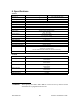
5.1 Equipment Required
•
13.8 VDC (nominal) car battery, or
13.8 VDC/20A regulated power supply (In
the case the unit is not installed in a vehicle)
•
In-line watt meter (50W range)
•
Radio service monitor (IFR or equivalent).
•
Cable with mini-UHF male connector to
connect Gemini
PD
to the service monitor.
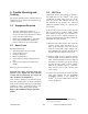
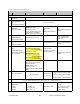
5.2 Basic Tests
Recommended checks:
1.
Transmit and Reverse power output
2.
Carrier frequency error
3.
Frequency deviation
4.
Receivers RSSI Check
5.
Link test between Gemini and the base sta-
tion.
6.
GPS test (not required on Gemini
PD
Lite
model).
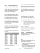
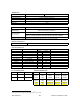
Refer to Table 5 for checks 1 to 5.
Important note: Before proceeding make sure
that the service monitor has been calibrated
recently and has warmed up for at least the
time specified by its manufacturer.
Some reported frequency and deviation prob-
lems have actually been erroneous indications
from service monitors that have not adequately
warmed up. This is particularly likely when
field service is done during winter months
Refer to the WinRIS section for function
details
5.3 GPS Test
About three minutes after ignition is turned-on,
the PWR LED on the Gemini
PD
front panel
should flash in amber color at the rate of one
pulse per second.
1
This indicates that the GPS
has acquired the sky position of a sufficient
number of satellites to arrive at a ground posi-
tion solution.
If the GPS has a good view of the sky and still
has not generated any position solution within
three minutes (it may take up to 10 minutes or
more if the sky view is partially blocked.), the
following trouble-shooting procedures should be
undertaken to isolate the fault:
1) Disconnect the GPS antenna cable connector
from the Gemini radio and check for + 5
VDC on the center pin of the GPS antenna
connector on the radio using a Digital volt-
meter (DVM). If the voltage is present, do not
reconnect the cable and proceed to step 2.
2) With the DVM, measure resistance between
the shell and the center conductor of the GPS
cable, resistance should be between 100 and
300 Ohms, if it measures open or short circuit
the GPS antenna is either a passive antenna
which is the WRONG type, or a defective
active antenna, replace with a known good
active antenna.
3) Connect the new antenna to Gemini and wait
about three minutes for the POSITION
ACQUIRED indicator to start flashing on
Gemini
PD
, if not, the Gemini radio or its GPS
receiver is defective
1
Lit green and flashing amber for the 800MHz model un-
der 2% duty cycle limit.