
Installation Guide

120 20110-142 Gemini
PD
Installation Guide
10
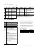
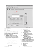
Table 1 - Gemini
PD
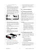
LEDs indications
Gemini
PD
LEDs indications
Power-on Sequence (LEDs are paired) Normal Operation (LEDs are independent)
PWR RX / TX Indication PWR Indication RX / TX Indication
Red Red
Normal boot-up start
(10 to 27 sec.)
Green* Normal ready state Off No network activity
Amber Off
Then 8 seconds to
completing boot-up
Normal
Green Off Normal state
Amber*
1 Pulse/sec.
Sufficient satellites
acquired by GPS
Green
Receiving packets
“DBA sync” allows transmit
Red Off Hardware failure Amber
Receiving packets
“DBA out-of-sync” prevents
transmit
Errors
Slow
Red/Green
Red
Software failure
(firmware erased)
Red Transmitting
Special
Fast
Red/Green
Red
Programming in
progress
* For 800MHz model (using 25% duty cycle limit)
PWR lit Green / Flashing Amber = normal indication (GPS 1pulse per sec.)
PWR lit Amber / Flashing Green = exceeded duty cycle (GPS 1pps)
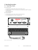
3.2 DTE Port Interface
For all three ports:
DE-9 F
pin #
Function
1
DCD – from Gemini
PD
, normally asserted
2 RXD – data from Gemini
PD
3 TXD – data to Gemini
PD
4 DTR – to Gemini
PD
, handshaking
5 Ground
6 DSR – from Gemini
PD
, tied to VCC
through current limiting resistor
7 RTS - to Gemini
PD
, handshaking
8 CTS – from Gemini
PD
, handshaking
9 AUX - auxiliary input to GeminiPD,
(for port 2: “Officer requires assistance”
Alarm input)
It may be activated by (normally open) dry
contact pull-up to the port’s DSR output. It
may also tolerate user pull-up to external
+12 VDC (car battery), but an isolated dry
contact is preferred due to the risk of
noise-related false alarms caused by the
vehicle’s electrical system.
A +3 to +12 V signal at this pin will send a
DMP
“x”
(On) message to the base.
An open or ground signal will send a DMP
“y”
(Off) message.
Messages are only sent when a signal
transition occurs.
See Appendix “A” on page 24 for further
details.
We recommend the use of a shielded 9-wire ca-
ble with all pins connected. These ports can be
used for unit configuration, maintenance & ad-
justment as well to connect user applications.
3.2.1 RS-232 Interface Signal Levels
In the descriptions of data signals, the following
conventions are used:
Table 2 - RS-232 Signal Levels
Term
Alternates
Signal level
1 asserted, spacing +3 to +15 V
OFF
dropped, marking
-3 to -15 V