
Installation Guide

120 20110-142 Gemini
PD
Installation Guide
5
•
Do not overtighten self-
tapping screws.
1.
Once you have found a suitable mount-
ing position for Gemini
PD
, hold the unit
and the unattached mounting bracket in
the proposed mounting position and
check that there is clearance behind the
unit for the heatsink, cables, etc. Check
that the position provides a large enough
flat surface that the bracket will not be
distorted when installed.
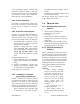
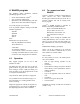
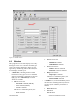
Figure 1 - Mounting plate and slot dimensions
2.
Using the installation bracket as a tem-
plate, mark the four locations for drilling
(see Figure 1). Again, ensure that drilling
at the selected points is safe and will not
cause damage.
3.
Indent the drilling positions with a center
punch.
4.
Drill holes sized for the self-tapping
screws or for the nuts, bolts and lock
washers used.
Caution:
Slightly reduce the size of the
drilled holes when using self-tapping
screws in thin metal.
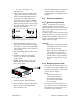
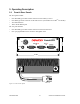
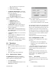
Figure 2 - Bracket installation
5.
Install the bracket without distorting.
6.
Securely mount Gemini
PD
to the installed
bracket using the four supplied 8x40
black machine screws.
7.
Drill any additional holes as required for
routing all cables and fit holes with
suitable grommets or bushings whenever
required.
2.4
Electrical installation
2.4.1 Electrical requirements
Gemini
PD
is designed to operate from a
13.8Vdc nominal car battery (negative
ground) and requires currents up to 15.0A. It
will tolerate a supply voltage range of 10.9
volts to 16.3 volts.
In vehicles with a 24 VDC electrical system
(mostly in trucks), it is essential to provide a
suitably rated 24/12 VDC converter to iso-
late the unit from the battery and protect it
against excessive voltage.
Warnings:
Application of more than 16.3 VDC
will damage Gemini
PD
and is not
covered by the warranty.
Always disconnect GeminiPD’s DC
power lead before connecting a
second battery, using power from
another vehicle or power boosting
(e.g. when “jump starting” the ve-
hicle).
2.4.2 Routing of power cable
1.
Start by disconnecting the vehicle’s bat-
tery unless specifically prohibited from
doing so by the customer, vehicle manu-
facturer, agent or supplier.
Note:
In this event, exercise ex-
treme caution throughout
the installation and fit the
fuse only when the installa-
tion is complete.
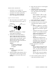
2.
The 22 feet (6.7 meters) long power ca-
ble consists of three wires attached to a
Packard Electric “Weather-Pack” con-
nector (DC power Connector).
2.5"
6.0"
1.0"
0.2"