
User's Manual

122 20130-005
G3 Installation Guide
16
3. Operating Description
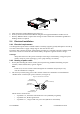
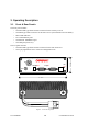
3.1 Front & Rear Panels
The front panel includes:
•
One mini-UHF type female antenna connector for the auxiliary receiver
•
One SMA type female connector for the GPS receiver (not installed on G3 Lite model)
•
Three LED indicators
•
Two DE-9F RS232 ports
•
One Ethernet 10/100BaseT port
•
One USB port (future use)
The rear panel includes:
•
One mini-UHF type female antenna connector for the main transceiver
•
One 3-pin pigtailed DC Power connector with ignition sense
Figure 5 - Front and rear panels
®
USB
RX
GPS
*
PWR
RX
TX
PGM
DEV-1
DEV-2
6.000"
2.000"
ETH
LNK
ACT