
Installation Guide

156-90000-508 G3
Installation Guide
10
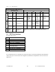
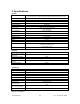
Table 1 - G3
LEDs indications
G3
LEDs indications
Power-on Sequence (LEDs are paired,
LNK always off)
Normal Operation (LEDs are independent)
PWR RX / TX Indication PWR Indication
RX /
TX
Indication
LNK/
ACT
Indication
Red Red Normal boot-up start Green
*
Normal
ready state
Off
No net-
work activ-
ity
Off
No network
activity
Amber Off completing boot-up
Normal
Green Off Normal state
Amber*
1
Pulse/sec.
Sufficient
satellites
acquired by
GPS
Green
Receiving
packets
“DBA
sync”
allows
transmit
Green
Ethernet net-
work set
Red Off Hardware failure Amber
Receiving
packets
“DBA out-
of-sync”
prevents
transmit
Errors
Slow
Red/Green
Red
Software failure
(firmware erased)
Red
Transmit-
ting
Special
Fast
Red/Green
Red
Programming in
progress
PWR lit Green / Flashing Amber = normal indication (GPS 1pulse per
sec.)
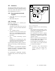
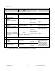
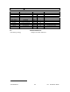
3.2 DTE Port Interface
For DEV1,DEV2 ports:
DE-9 F
pin #
Function
1
DCD – from G3
, normally asserted
2 RXD – data from G3
3 TXD – data to G3
4 DTR – to G3
, handshaking
5 Ground
6 DSR – from G3
, tied to VCC through
current limiting resistor
7 RTS - to G3
, handshaking
8 CTS – from G3
, handshaking
9 AUX - auxiliary input to G3
.
We recommend the use of a shielded 9-wire cable with all pins connected and shielded USB and Ethernet
cables. These ports can be used for unit configuration, maintenance & adjustment as well to connect user
applications.