
Installation Guide

156 90000-508 G3
Installation Guide
7
G
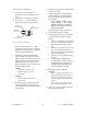
2.2.1
≥5/8λ
800MHz: 9"/23cm
R
T
50cm
19.7in.
≥24in.
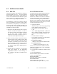
2.5 Antenna
The main transmitter antenna must be vehi-
cle-mounted to provide a separation distance
of 50 cm or more from all persons to avoid
radio related effects (see 2.2.1).
2.5.1 Recommended tools and
supplies
• circle cutter, hole saw or socket punch
for antenna
• Mini-UHF Crimp tool
2.5.2 Planning
Referring to Figure 4, G3
commonly uses
three separate antennas:
• “T” - Main transceiver -
Constraints are the limit of 50 cm (see
section 2.5 above) and omni-directional
factors
• “R” - Auxiliary receiver –
Constraints are the receiver spacing of at
least 5/8 λ (wavelength) from trans-
ceiver antenna and omni-directional re-
quirements
• “G” - Global Positioning System
(GPS)*
Constraints are TX spacing of at least
24-in/60.96 cm from all transmitting an-
tennas and a clear view of the sky.
For the optimum antenna spacing at the fre-
quency you are using, consult System Engi-
neering.
For installation of ground-plane dependent
antennas, the center of the metal surface
used for mounting is preferable for best
omni-directional pattern.
For ground-plane independent antennas,
installation may be close to the edges of the
surface.
Figure 4 - Antenna spacing
Install the antennas in one of the following
positions:
- Most preferred for all antennas: center-
line of roof. For transmitter antenna, it is
the ONLY acceptable position.
- Less preferred for receiver antenna:
trunk lid, providing distance to transmit-
ting antenna is respected whether lid is
opened or closed.
- Much less preferred, but permissible for
receiver antenna: left or right rear fend-
ers, just in back of rear window
- Least preferred, but permissible for re-
ceiver antenna: left or right front fend-
ers, ahead of windshield
Note:
Proximity to other vehicle-mounted
antennas may cause mutual inter-
ference especially at higher fre-
quencies.