
User Manual
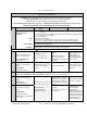
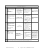
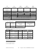

Table Of Contents

120 20195-100 Preliminary Paragon4 – UHF, 700, & 800MHz User Manual
23
CHECKLIST B (Paragon4) cont’d
General Check out (part 2 of 2)
Step ACTION
Expected Results at 25°C
MEASURE WITH IF NOT?
7
Low Frequency Balance
Under Test Tone section
select
Random Data
and press “Execute”/
a) Record deviation level
read from step 6
b) Record deviation read
from TX Random test
c) Difference between
a) and b) should be:
< 2.5 kHz
Service monitor set to read
deviation
(IF filter set to Mid or 30
kHz position, all audio
filtering disabled )
Refer to Section Error!
Reference source not
found.
8
12 dB SINAD
(Dataradio wide band meas-
urement method: no audio
filtering)
Set TX deviation to ±3 kHz.
Better than -108 dBm
including cable loss
(Typically -109 to -110 dBm)
- Backplane corresponding
to the receiver being
verified: J1 (RX1) or J5
(RX2),
Pin 6 (see Figure 3)
- Service monitor (IFR) set
to SINAD
IFR IF filter set to MID
position or 30 kHz wide
filter.
Refer to section Error!
Reference source not
found.
9
Receiver distortion
(Dataradio wide band meas-
urement method: no audio
filtering)
- Set service monitor RF
Gen output to –70 dBm
Deviation level as per
SINAD above.
≤ 5.5 %
(Typically < 3.5 %)
- Backplane corresponding
to the receiver being
verified:
J1 (RX1) or J5 (RX2), Pin
6 (see
Figure 3)
- Service monitor (IFR) set
to DISTORTION.
- IFR IF filter set to MID
position or 30 kHz wide
filter.
10
RSSI
Apply to each receiver input
the following RF level:
UHF & 800: -110dBm
UHF & 800 MHz:
2.0 VDC (+/- 0.3VDC)
BSC must be connected to
the radio during the
measurements
- Backplane corresponding
to the receiver being
verified:
- J1 (RX1) or J5 (RX2), Pin
5 (see
Figure 3)
- DC Voltmeter measure-
ment
Refer to section Error!
Reference source not
found. for all models.
Refer to factory techni-
cal support only if RX
data performance deg-
radation is noticed
combined with out-of-
tolerance RSSI read-
ings.
11
Verify power supply connections & terminals torque settings (see paragraph 2.4.1.1)