
User Manual
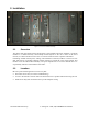
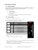
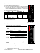
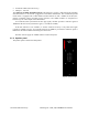
Table Of Contents

120 20195-100 Preliminary Paragon4 – UHF, 700, & 800MHz User Manual
10
3. Operating Description
3.1 Radio Assembly
The Radio assembly component of each Paragon4 product – UHF, 700, and 800MHz – is made up of
high performance synthesized radio base station designed for single operation. The Radio Assembly’s
modules are commonly installed in a standard, 19-inch wide rack frame.
The complement of modules is:
• 1 x Receiver module
• 1 x Exciter module
• 1 x BSC (controller-modem)
• 1 x Speaker panel
and mounted on the rack (normally immediately below the Paragon4 radiomodem):
• 1 x Dual Power Supply module
3.1.1 Receiver module
For locating the module, refer to Figure 2 above.
The receiver has several front panel controls and indicators. These are:
• LEDs -Four LEDs as for the SDR-Rx receiver module:
Green normal operation
Amber bootloader program running
PWR LED
Red malfunction / reset
Green PLL locked
LOCK
LED
Red PLL not locked
Green
RF carrier signal on audio channel 1 is above manu-
ally adjusted mute threshold
1 LED
Off RF carrier signal on audio channel 1 is below manually
adjusted mute threshold
Green RF carrier signal on audio channel 2 is above manu-
ally adjusted mute threshold
2 LED
Off
RF carrier signal on audio channel 2 is below manually
adjusted mute threshold
• RCVR GATE LEVEL - Mute threshold adjustment. It sets the RF signal
level required to open the mute gate and allow audio to pass to the
speaker
1
.
• 1 / 2 Switch – Manual selection of Channel 1 or 2 audio
Figure 5 - Receiver module
• Volume - The audio output delivers up to 1 watt to the speaker. Always set volume knob to
minimum when not in use to reduce current consumption.
• NORM-MON Switch – Manual selection between audio unmuted (continuous monitor) or when
audio is above the manually adjusted mute threshold
LOCK
PWR
RCVR
GATE
LEVEL
VOLUME
NORM -
Diversit
y
SDR Rx