
User Manual
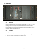
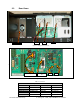
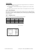
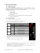
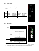
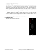
Table Of Contents

120 20195-100 Preliminary Paragon4 – UHF, 700, & 800MHz User Manual
6
2.3 Rear Views
Figure 2 - Paragon4 unit rear view
Figure 3 - Backplane
Table 2 - Test Points
Backplane Test Points Rx/Tx
Test J9 Access port Alternate Pinout
Ground Pin 14 J18, J19 – Pin 3
SINAD &Distorsion RX1 -Differential 1P-3; 1N-8 J18- Pins 1,2
SINAD &Distorsion RX2-Differential 2P-4; 2N-9 J19 – Pins 1,2
RSSI RSSI 1 -Differential 1P-1; 1N-6 J18 – Pins 4,5
RSSI RSSI 2-Differential 2P-2; 2N-7 J19 – Pins 4,5
.
10-amp fuse
J18
Access port
J9
J19
RX 1&2
BSC
Exciter
Speaker Panel