
User's Manual

001-2019-500 Rev 0
Paragon4 – UHF, 700 & 800MHz User Manual
69
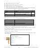
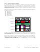
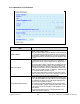
Figure 61 - Layer, protocols, and interfaces applicable to Dataradio implementation
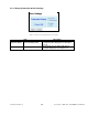
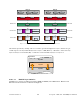
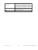
All statistics presented by CalAmp follow a convention presented in Figure 62. Layer n statistics are giv-
en with respect to the layer immediately below it: layer n-1. RX (Receive) or IN refers to data received by
layer n from layer n-1. Transmit (TX) or OUT refers to data transmitted by layer n to layer n-1.
Figure 62 - RX and TX Convention
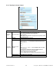
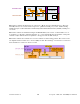
6.10.1.1.1 Datalink Layer Statistics
Datalink layer comprises two Ethernet interfaces (ETH1 and ETH2) and an RF interface. Ethernet1 and
Ethernet2 interfaces statistics are illustrated in Figure 63.
Layer N
Layer N+1
Layer N-1
RX/IN
TX/OUT
Convention
TRANSPORT LAYER
NETWORK LAYER
DATALINK LAYER
PHYSICAL LAYER
HTTP
SNMP
FTP
APPLICATION LAYER
HOST A
TCP
UDP
IP
TRANSPORT LAYER
NETWORK LAYER
DATALINK LAYER
PHYSICAL LAYER
ETH
2
ETH
1
RF
-
AIRLINK
RF
-
OIP
Layer P
/
D Interface
Layer D
/
N Interface
Layer N
/
T Interface
ETH PHY
ETH PHY
EDBA PHY
FEC
Layer T
/
A Interface
APPLICATION LAYER
HTTP
SNMP
FTP
HOST B
TCP
UDP
IP
ETH
2
ETH
1
RF
-
AIRLINK
RF
-
OIP
Layer P
/
D Interface
Layer D
/
N Interface
Layer N
/
T Interface
ETH PHY
ETH PHY
EDBA PHY
FEC
Layer T
/
A Interface
TRANSPORT MEDIA