
User's Manual

001-2019-500 Rev 0
Paragon4 – UHF, 700 & 800MHz User Manual
7
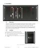
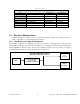
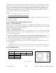
Table 2 - Test Points
Backplane Test Points Rx/Tx
Test
J9 Access port
Alternate Pinout
Ground
GND
Pin 14
J18, J19 – Pin 3
SINAD & Distortion
RX1 -Differential
1P-Pin3; 1N-Pin8
J18- Pins 1,2
SINAD & Distortion
RX2-Differential
2P-Pin4; 2N-Pin9
J19 – Pins 1,2
RSSI
RSSI 1 -Differential
1P-Pin1; 1N-Pin6
J18 – Pins 4,5
RSSI
RSSI 2-Differential
2P-Pin2; 2N-Pin7
J19 – Pins 4,5
TX Audio
TXAP-Differential (+ve side only)
1P-Pin 5
Key Transmitter
/TXKEY-single ended
Pin 15
4.4 Electrical Configurations
Standard 120/240 VAC electrical power is required. It should be capable of providing at least 6A
(120V) or 4A(240V) to power the Paragon4 base station.
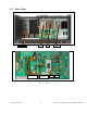
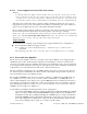
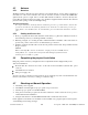
4.4.1 Standard Power Supply Configurations
The standard configuration for supplying the required +13.8 VDC to the Paragon4 base station and the
Crescend Power Amplifier is shown in the two figures below, a simple block diagram and a virtual rack-
mount installation. The base station and the power amplifier module receive 13.8 VDC power inputs
from the ICT22012-70N power supply module powered at 120 VAC.
Figure 5 – Simple AC-to-DC power supply configurations: Block Diagram
120 VAC
AC/DC Power Supply
ICT22012-70N
(34 Amp DC Continuous)
PA
Crescend
Paragon4
Base Station