
User's Manual

001-2019-500 Rev 0 Paragon4 – UHF, 700 & 800MHz User Manual
87
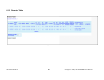
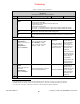
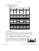
Table 8 - Checklist A (After installation)
CHECKLIST A
(Paragon4)
Recommended Check out after Installation
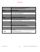
Step ACTION
EXPECTED RESULTS at 25°C
MEASURE WITH IF NOT?
1
Normal Powe
r
-up Sequence
BSC2
PWR LED lights red for up to 5 second, turns amber for up to 5 seconds second,
and stays green thereafter.
TX LED flashes green within 90 seconds after reset
RX LED remains OFF
STATUS LED remains OFF
ETH 1 LED – if connection present – lights green. Flashes amber with activity
ETH 2 LED – If connection present – lights green. Flashes amber with activity
RX
POWER and LOCK LEDs must remain steady green
TX
POWER and LOCK LEDs must remain steady green
ON LED lights red for one second, turns OFF for 10 seconds, and stays red the-
reafter
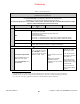
For steps below, refer to Radio (RF Tests) Web Page
2
Power Amplifier
Output Power
Under Test Tone sec-
tion select
Unmodulated
and click Execute
UHF: 100W
(factory configurable from 50W)
700 or 800 MHz: 70 watts
(factory configurable from 35W)
Tolerance: +15% -20%
Service monitor set to
read power
or
150W in-line wattme-
ter installed as close
as possible to the unit
antenna connector.
Verify if PA front
panel LEDs are
off, except PWR
LED on green.
If not
1
Check for
bad connections,
damaged coax
cable, etc.
Also check power
at exciter module
output. Should be
in the range of
100-200mW.
If OK, PA may be
at fault. Contact
CalAmp support.
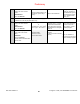
3
Transmitter Reflected
Power
Under Test Tone sec-
tion select
Unmodulated
and click Execute
< 5% of forward power or as speci-
fied by System Engineering.
15W in-line wattmeter
Verify if PA front
panel LEDs are
all OFF except
PWR LED (green)
If not, check for
bad connections,
damaged coax
cable, etc.
4
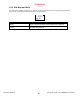
RF Link test between Paragon4 unit(s) and mobile unit(s) (PING test as per paragraph 7.4.1)
1
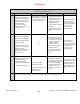
(unless unit has been set a lower value). Note that readings less than 100 watts for UHF or 70 watts for the 700 and
800 MHz models, may be due to losses in cables used for testing. Check also your wattmeter frequency calibration
curve. Do not be too ready to condemn the transmitter or the RF feedline & antenna installation.
Preliminary