
User's Manual

001-2019-500 Rev 0 Paragon4 – UHF, 700 & 800MHz User Manual
9
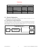
Prior to powering up, ensure that both voltage selection switches (located on the back) are set to the
proper voltage for your operation. Available settings are 120 or 220 volts. The ICT 22012-70N metal
enclosure is internally connected to earth ground via its individual, rear-connected, 120VAC (NEMA 5-
15p plug to IEC 60320-C19 receptacle) power cord. Therefore, the system must be operated from an out-
let with a proper grounding connection.
Cautions:
It is important that the side ventilation holes are unobstructed at all times. Do not oper-
ate this unit in a completely enclosed cabinet.
High current leakage, use only the cord supplied with this equipment for power.
If accessing modules, power at both the switch and the AC inlet must be disconnected to
ensure operator safety.
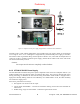
4.4.2.1 Fuse Replacement
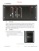
To access the fuses, the ICT unit cover must be removed. Ensure that power (cable, battery or solar
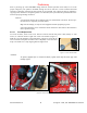
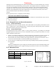
source) is removed. Remove eight side screws and washers (Figure 7).
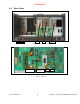
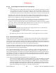
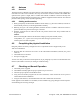
Slide the cover off. Referring to the illustrations in Figure 8, locate the two
32V 35A fuses and replace as needed. Once completed, reverse the above
steps to re-install cover. Only finger tighten the eight screws.
Figure 7 - Screw removal detail
Caution:
To protect against fire or electrical shock, replace with only the same type and
ratings of fuse.
Figure 8 - Fuses Location
Preliminary