
User's Manual

001-2019-500 Rev 0 Paragon4 – UHF, 700 & 800MHz User Manual
64
• When complete, use the “Save As” command.
• The file name is case-sensitive and spaces are not allowed.
• The file name should be saved under .pli extension.
• The file should be uploaded into a unit using FTP transfers.
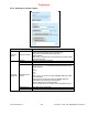
• The file’s name should be entered under “Analog monitoring 1 calibration” (and/or “Analog monitor-
ing 2 calibration”) field on the Diagnostic page of the Paragon4 web interface.
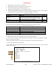
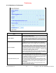
Table 6 - PLICC Syntax
Syntax Description
// <comment> Comments. Optional
[c] <name>
Descriptive name of the look-up table (string of 80 characters
max). This field will appear under the “description” field on
the Diagnostics Settings” page of the Pargon3 web interface.
Optional
[u] <unit> Unit of measure (string of 16 char maximum). Optional
[n] <index> Number of entries in the table (2 minimum, 50 maximum). Required
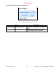
Failure to comply with the guidelines described above may result in the following errors:
Table 7 - Possible Error messages
Error Description
No file found The file name entered is not found on the unit.
Bad header or bad file format found. Syntax Error .
No data found. No data entered in the file (less than 2 data points).
More than 50 segments found in file. The file counts more than 50 data points.
Duplicate X values found in data. The file contains duplicate X
in
values.
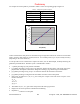
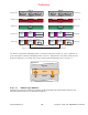
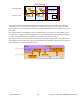
A sample calibration file is presented in Figure 55. Please note the following:
1. “Volts to watts conversion” will appear under the “description” field on the “Diagnostics Settings”
page of the Pargon3 web interface.
2. This look-up table contains a set of values in Volts with their corresponding values in Watts.
3. This look-up table contains five data points.
4. The number of data points should correspond to the index (entered under [n]). All X
in
entries (voltage
values) must be unique.
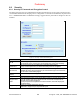
// file name: sample_calibration_file.pli
// Revision: N.NN
// Date: YYYY/MM/DD
// Other Comments
[c]Volts to watts conversion
[u]Watts
[n]5
0.000 0.0
0.200 1.0
0.375 2.0
0.530 3.0
0.530 4.0
Figure 55 - Sample calibration file
2
3
1
4
Preliminary